Infiniti QX56 (Z62). Manual - part 1379


  Index      Infiniti     Infiniti QX56 (Z62) - service repair manual 2011 year


Search            


Content   ..  1377  1378  1379  1380   ..


Infiniti QX56 (Z62). Manual - part 1379


ROAD WHEEL

WT-63

< PERIODIC MAINTENANCE >

C

D

F

G

H

I

J

K

L

M

A

B

WT

N

O

P

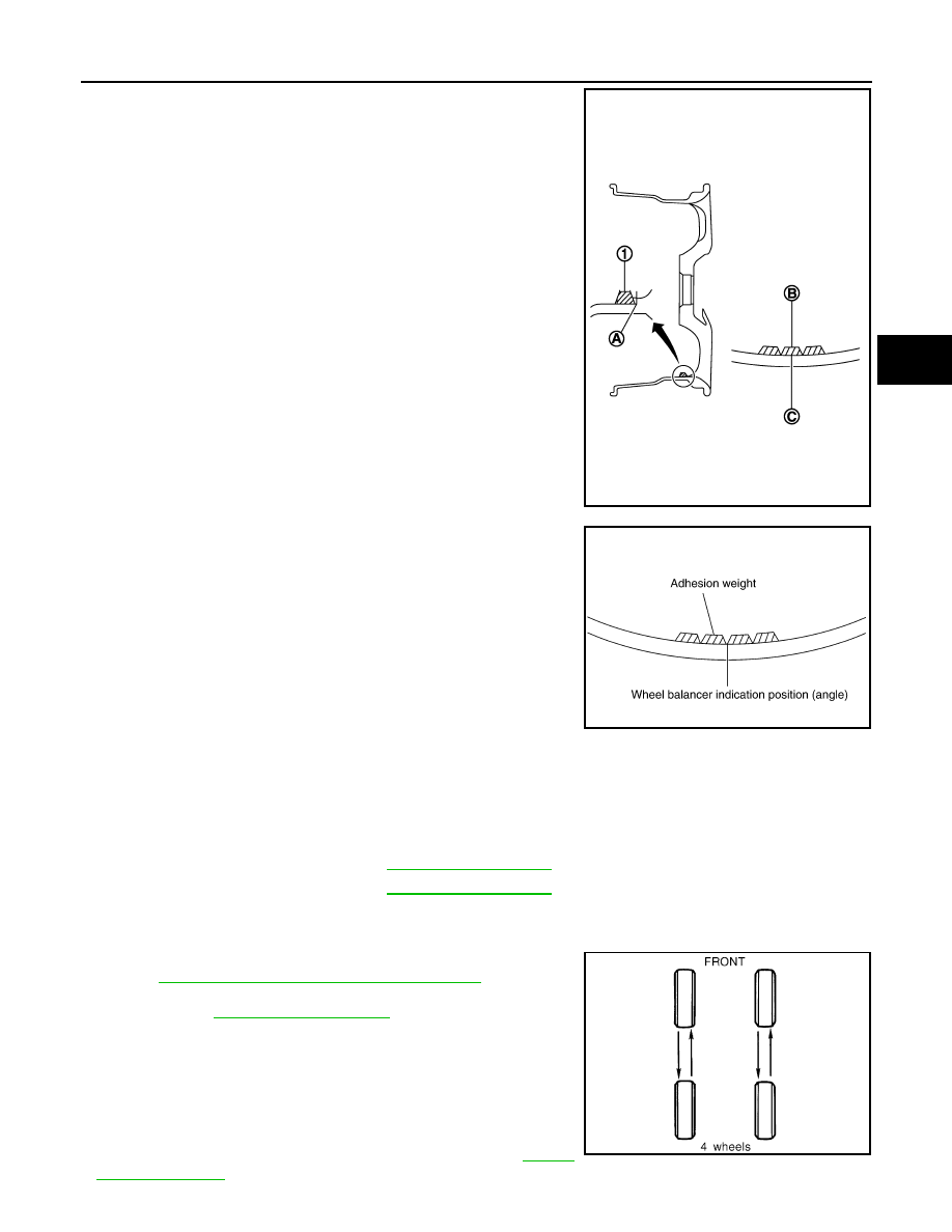
• When installing balance weight (1) to road wheels, set it into

the grooved area (A) on the inner wall of the road wheel as
shown in the figure so that the balance weight center (B) is
aligned with the tire balance machine indication position
(angle) (C).

CAUTION:

• Always use genuine NISSAN adhesion balance weights.
• Balance weights are non-reusable; always replace with

new ones.

• Never install more than four sheets of balance weight.

c.

If calculated balance weight value exceeds 50 g (1.76 oz), install
two balance weight sheets in line with each other as shown in
the figure.

CAUTION:

Never install one balance weight sheet on top of another.

3.

Start the tire balance machine again.

4.

Install drive-in balance weight on inner side of road wheel in the
tire balance machine indication position (angle).

CAUTION:

Never install more than two balance weight.

5.

Start the tire balance machine. Check that the inner and outer
residual unbalance value is within the allowable unbalance
value.

CAUTION:

If either residual unbalance value exceeds limit, repeat installation procedures.

Tire Rotation

INFOID:0000000006225546

• Follow the maintenance schedule for tire rotation service intervals.

Refer to 

MA-4, "Explanation of General Maintenance"

.

• When installing the wheel, tighten wheel nuts to the specified

torque. Refer to 

WT-64, "Exploded View"

.

CAUTION:

• When installing wheels, tighten them diagonally by dividing

the work two to three times in order to prevent the wheels
from developing any distortion.

• Be careful not to tighten wheel nut at torque exceeding the

criteria.

• Use NISSAN genuine wheel nuts for aluminum wheels.

• Perform the ID registration, after tire rotation. Refer to 

WT-29,

"Work Procedure"

.

JPEIC0040ZZ

Allowable unbalance value

Dynamic (At flange)

: Refer to 

WT-69, "Road Wheel"

.

Static (At flange)

: Refer to 

WT-69, "Road Wheel"

.

PEIA0033E

SMA829C

WT-64

< REMOVAL AND INSTALLATION >

ROAD WHEEL TIRE ASSEMBLY

REMOVAL AND INSTALLATION

ROAD WHEEL TIRE ASSEMBLY

Exploded View

INFOID:0000000006225547

Removal and Installation

INFOID:0000000006225548

REMOVAL

1.

Remove wheel nuts.

2.

Remove tire assembly.

INSTALLATION

Note the following, install in the reverse order of removal.
• When replacing or rotating wheels, perform the ID registration. Refer to 

WT-29, "Work Procedure"

.

Inspection

INFOID:0000000006225549

ALUMINUM WHEEL

1.

Check tires for wear and improper inflation.

2.

Check wheels for deformation, cracks and other damage. If deformed, remove wheel and check wheel
runout.

a.

Remove tire from aluminum wheel and mount on a tire balance machine.

b.

Set dial indicator as shown in the figure.

c.

Check radial runout, if the lateral deflection (A) or vertical deflec-
tion (B) for radial runout value exceeds the limit, replace alumi-
num wheel.

1.

Tire assembly

Refer to 

GI-4, "Components"

 for symbols in the figure.

JPEIC0088GB

Limit

Lateral deflection (A)

: Refer to 

WT-69, "Road Wheel"

.

Vertical deflection (B)

: Refer to 

WT-69, "Road Wheel"

.

SEIA0737E

LOW TIRE PRESSURE WARNING CONTROL UNIT

WT-65

< REMOVAL AND INSTALLATION >

C

D

F

G

H

I

J

K

L

M

A

B

WT

N

O

P

LOW TIRE PRESSURE WARNING CONTROL UNIT

Exploded View

INFOID:0000000006225550

Removal and Installation

INFOID:0000000006225551

REMOVAL

1.

Remove the glove box assembly. Refer to 

IP-14, "Removal and Installation"

.

2.

Remove the instrument lower panel RH. Refer to 

IP-14, "Removal and Installation"

3.

Disconnect low tire pressure warning control unit connector.

4.

Remove the low tire pressure warning control unit control unit.

INSTALLATION

Note the following, install in the reverse order of removal.
• Perform ID registration after replacing low tire pressure warning control unit. Refer to 

WT-29, "Work Proce-

dure"

.

1.

Low tire pressure warning control unit 2.

Bracket

: Vehicle front

Refer to 

GI-4, "Components"

 for symbols in the figure.

JPEIC0072ZZ

WT-66

< REMOVAL AND INSTALLATION >

TRANSMITTER

TRANSMITTER

Exploded View

INFOID:0000000006225552

Removal and Installation

INFOID:0000000006225553

REMOVAL

1.

Deflate tire. Unscrew transmitter retaining nut and allow transmitter to fall into tire.

2.

Gently bounce tire so that transmitter falls to bottom of tire.
Place on tire changing machine and break both tire beads
ensuring that the transmitter remains at the bottom of the tire.

3.

Turn tire so that valve hole is at bottom and bounce so that
transmitter (1) is near valve hole. Carefully lift tire onto turntable
and position valve hole (and transmitter) 270 degree from
mounting/dismounting head (2).

4.

Lubricate tire well and remove first side of the tire. Reach inside
the tire and remove the transmitter.

INSTALLATION

JPEIC0081GB

1.

Transmitter

2.

Grommet seal

3.

Valve nut

4.

Valve core

5.

Cap

Refer to 

GI-4, "Components"

 for symbols in figure.

SEIA0047E

JPEIC0014GB


Content   ..  1377  1378  1379  1380   ..