Infiniti QX56 (Z62). Manual - part 1362


  Index      Infiniti     Infiniti QX56 (Z62) - service repair manual 2011 year


Search            


Content   ..  1360  1361  1362  1363   ..


Infiniti QX56 (Z62). Manual - part 1362


WCS

SEAT BELT BUCKLE SWITCH SIGNAL CIRCUIT

WCS-41

< DTC/CIRCUIT DIAGNOSIS >

C

D

E

F

G

H

I

J

K

L

M

B

A

O

P

SEAT BELT BUCKLE SWITCH SIGNAL CIRCUIT

Component Function Check

INFOID:0000000006222691

1.

CHECK COMBINATION METER INPUT SIGNAL

Select the “Data Monitor” for the “METER/M&A” and check the “BUCKLE SW” monitor value.

>> INSPECTION END

Diagnosis Procedure

INFOID:0000000006222692

1.

CHECK COMBINATION METER INPUT SIGNAL

1.

Turn ignition switch ON.

2.

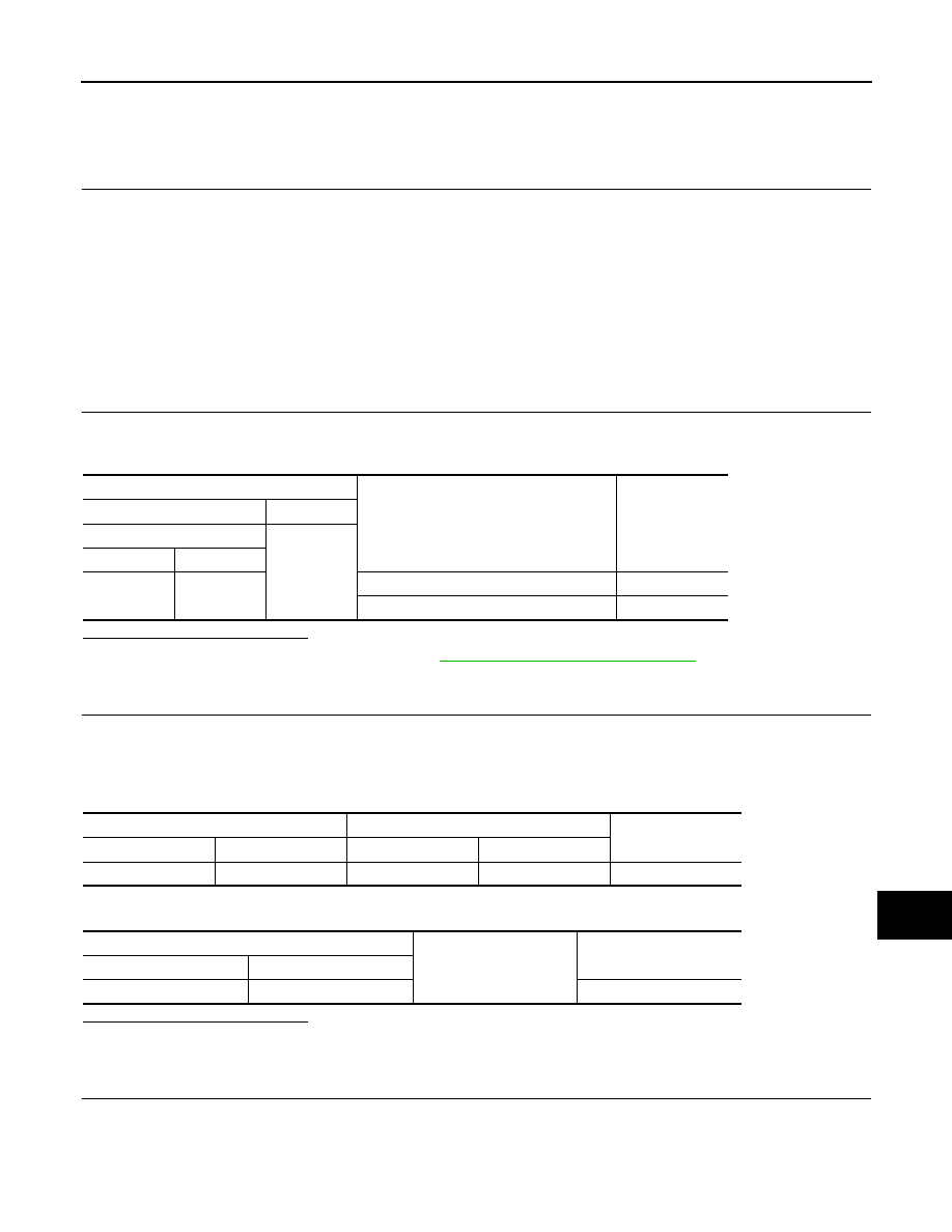
Check voltage between combination meter harness connector and ground.

Is the inspection result normal?

YES

>> Replace combination meter. Refer to 

MWI-85, "Removal and Installation"

.

NO

>> GO TO 2.

2.

CHECK SEAT BELT BUCKLE SWITCH CIRCUIT

1.

Turn ignition switch OFF.

2.

Disconnect combination meter connector and seat belt buckle switch (driver side) connector.

3.

Check continuity between combination meter harness connector and seat belt buckle switch (driver side)
harness connector.

4.

Check harness continuity between combination meter harness connector and ground.

Is the inspection result normal?

YES

>> GO TO 3.

NO

>> Repair harness or connector.

3.

CHECK SEAT BELT BUCKLE SWITCH GROUND CIRCUIT

Check harness continuity between seat belt buckle switch (driver side) harness connector and ground.

BUCKLE SW

When seat belt is fastened

: Off

When seat belt is unfastened

: On

Terminals

Condition

Voltage

(Approx.)

(+)

(-)

Combination meter

Ground

Connector

Terminal

M34

35

When driver seat belt is fastened

12 V

When driver seat belt is unfastened

0 V

Combination meter

Seat belt buckle switch (driver side)

Continuity

Connector

Terminal

Connector

Terminal

M34

35

B76

3

Existed

Combination meter

Ground

Continuity

Connector

Terminal

M34

35

Not existed

WCS-42

< DTC/CIRCUIT DIAGNOSIS >

SEAT BELT BUCKLE SWITCH SIGNAL CIRCUIT

Is the inspection result normal?

YES

>> INSPECTION END

NO

>> Repair harness or connector.

Component Inspection

INFOID:0000000006222693

1.

CHECK SEAT BELT BUCKLE SWITCH (DRIVER SIDE)

1.

Turn ignition switch OFF.

2.

Disconnect the seat belt buckle switch (driver side) connector.

3.

Check continuity between terminals.

Is the inspection result normal?

YES

>> INSPECTION END

NO

>> Replace seat belt buckle (driver side). Refer to 

SB-8, "SEAT BELT BUCKLE : Removal and Instal-

lation"

.

Seat belt buckle switch (driver side)

Ground

Continuity

Connector

Terminal

B76

4

Existed

Terminal

Condition

Continuity

3

4

When seat belt is fastened

Not existed

When seat belt is unfastened

Existed

WCS

PARKING BRAKE SWITCH SIGNAL CIRCUIT

WCS-43

< DTC/CIRCUIT DIAGNOSIS >

C

D

E

F

G

H

I

J

K

L

M

B

A

O

P

PARKING BRAKE SWITCH SIGNAL CIRCUIT

Diagnosis Procedure

INFOID:0000000006222530

1.

CHECK COMBINATION METER INPUT SIGNAL

1.

Turn ignition switch ON.

2.

Check the voltage between combination meter harness connector and ground.

Is the inspection result normal?

YES

>> INSPECTION END

NO

>> GO TO 2.

2.

CHECK PARKING BRAKE SWITCH SIGNAL CIRCUIT

1.

Turn ignition switch OFF.

2.

Disconnect combination meter connector and parking brake switch connector.

3.

Check continuity between combination meter harness connector and parking brake switch harness con-
nector.

4.

Check continuity between combination meter harness connector and ground.

Is the inspection result normal?

YES

>> INSPECTION END

NO

>> Repair harness or connector.

Component Inspection

INFOID:0000000006222531

1.

CHECK PARKING BRAKE SWITCH

Check parking brake switch. Refer to 

BRC-118, "Component Inspection"

.

Is the inspection result normal? 

YES

>> INSPECTION END.

NO

>> Replace parking brake switch. Refer to 

PB-5, "Exploded View"

.

(+)

(

)

Condition

Voltage

(Approx.)

Combination meter

Ground

Connector

Terminal

M34

26

Ignition 
switch ON

When parking brake is applied

0 V

When parking brake is released

12 V

Terminals

Continuity

Combination meter

Parking brake switch

Connector

Terminal

Connector

Terminal

M34

26

M11

1

Existed

Terminals

Continuity

Combination meter

Ground

Connector

Terminal

M34

26

Not existed

WCS-44

< SYMPTOM DIAGNOSIS >

THE LIGHT REMINDER WARNING DOES NOT SOUND

SYMPTOM DIAGNOSIS

THE LIGHT REMINDER WARNING DOES NOT SOUND

Description

INFOID:0000000006222532

Light reminder warning chime does not sound even though headlamp is illuminated.

Diagnosis Procedure

INFOID:0000000006222533

1.

CHECK COMBINATION SWITCH (LIGHTING SWITCH) OPERATION

Check that the headlamps operate normally by operating the combination switch (lighting switch).

Do they operate normally?

YES

>> GO TO 2.

NO

>> Refer to 

EXL-113, "Symptom Table"

.

2.

CHECK DRIVER SIDE DOOR SWITCH SIGNAL CIRCUIT

Perform the check for the driver side door switch signal circuit. Refer to 

DLK-117, "Diagnosis Procedure"

.

Is the inspection result normal?

YES

>> GO TO 3.

NO

>> Repair harness or connector.

3.

CHECK DRIVER SIDE DOOR SWITCH

Perform a unit check for the driver side door switch. Refer to 

DLK-119, "Component Inspection"

.

Is the inspection result normal?

YES

>> Replace BCM. Refer to 

BCS-81, "Removal and Installation"

.

NO

>> Replace driver side door switch. Refer to 

DLK-254, "Removal and Installation"

.


Content   ..  1360  1361  1362  1363   ..