Infiniti QX56 (Z62). Manual - part 136


  Index      Infiniti     Infiniti QX56 (Z62) - service repair manual 2011 year


Search            


Content   ..  134  135  136  137   ..


Infiniti QX56 (Z62). Manual - part 136


SYSTEM

BRC-29

< SYSTEM DESCRIPTION >

[WITH VDC]

C

D

E

G

H

I

J

K

L

M

A

B

BRC

N

O

P

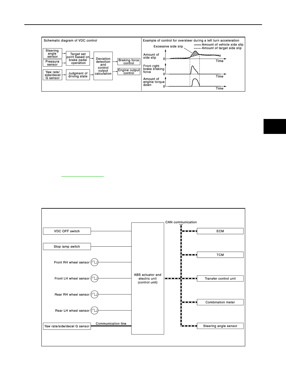
side/decel G- sensor and wheel sensor, vehicle driving conditions (conditions of understeer or oversteer) are
judged and vehicle stability is improved by brake force control on all 4 wheels and engine output control.

• Control unit portion automatically improves driving stability by performing brake force control as well as

engine output control, by transmitting drive signal to actuator portion according to difference between target
side slip amount and vehicle side slip amount

• VDC function can be switched to non-operational status (OFF) by operating VDC OFF switch. In this case,

VDC OFF indicator lamp turns ON.

• VDC function is not operate when 4WD mode is “4L”. (Models with 4WD system)
• VDC warning lamp blinking while VDC function is in operation and indicates to the driver that the function is

in operation.

• Slight vibrations are felt on the brake pedal and the operation noises occur, when VDC function operates.

This is not a malfunction because it is caused by VDC function that is normally operated.

• CONSULT-III can be used to diagnose the system diagnosis.
• Fail-safe function is adopted. When a malfunction occurs in VDC function, the control is suspended for VDC

function, TCS function, hill start assist function and brake limited slip differential (BLSD) function. The vehi-
cle status becomes the same as models without VDC function, TCS function, hill start assist function and
brake limited slip differential (BLSD) function. However, ABS function and EBD function are operated nor-
mally. Refer to 

BRC-25, "Fail-safe"

.

NOTE:
VDC has the characteristic as described here, but it is not the device that helps reckless driving.

SYSTEM DIAGRAM

NOTE:
Transfer control unit is applied to models with 4WD system.

INPUT SIGNAL AND OUTPUT SIGNAL

JPFIC0133GB

JPFIC0183GB

BRC-30

< SYSTEM DESCRIPTION >

[WITH VDC]

SYSTEM

Major signal transmission between each unit via communication lines is shown in the following table.

*1: Communication line between yaw rate/side/decal G sensor and ABS actuator and electric unit (control unit)
*2: Models with 4WD system

OPERATION CHARACTERISTICS

VDC Function That Prevents Oversteer Tendency

• During a cornering, brake force (brake fluid pressure) is applied on front wheel and rear wheel on the outer

side of turn. Moment directing towards the outer side of turn is generated. Oversteer is prevented.

• Changing driving lane on a slippery road, when oversteer tendency is judged large, engine output is con-

trolled as well as brake force (brake fluid pressure) of 4 wheels. Oversteer tendency decreases.

VDC Function That Prevents Understeer Tendency

Component

Signal description

Yaw rate/side/decel G sensor

Mainly transmits the following signals to ABS actuator and electric unit (control unit) via com-

munication line

*1

.

• Yaw rate signal
• Side G sensor signal
• Decel G sensor signal

ECM

Mainly transmits the following signals to ABS actuator and electric unit (control unit) via CAN 
communication.
• Accelerator pedal position signal
• Engine speed signal
Mainly receives the following signals from ABS actuator and electric unit (control unit) via CAN 
communication.
• Target throttle position signal

TCM

Mainly transmits the following signals to ABS actuator and electric unit (control unit) via CAN 
communication.
• Shift position signal

Transfer control unit

*2

Mainly transmits the following signals to ABS actuator and electric unit (control unit) via CAN 
communication.
• Current 4WD mode signal

Steering angle sensor

Mainly transmits the following signals to ABS actuator and electric unit (control unit) via CAN 
communication.
• Steering angle sensor signal

Combination meter

Mainly receives the following signals from ABS actuator and electric unit (control unit) via CAN 
communication.
• VDC warning lamp signal
• VDC OFF indicator lamp

JPFIC0135GB

JPFIC0136GB

SYSTEM

BRC-31

< SYSTEM DESCRIPTION >

[WITH VDC]

C

D

E

G

H

I

J

K

L

M

A

B

BRC

N

O

P

• During a cornering, brake force (brake fluid pressure) is applied on front wheel and rear wheel on the inner

side of turn. Moment directing towards the inner side of turn is generated. Understeer is prevented.

• Applying braking during a cornering on a slippery road, when understeer tendency is judged large, engine

output is controlled as well as brake force (brake fluid pressure) of four wheels. Understeer tendency
decreases.

TCS FUNCTION

TCS FUNCTION : System Description

INFOID:0000000006222573

• Wheel spin status of drive wheel is detected by wheel sensor of 4

wheels. Engine output and transmission shift status is controlled
so that slip rate of drive wheels is in appropriate level. When wheel
spin occurs on drive wheel, ABS actuator and electric unit (control
unit) perform brake force control of LH and RH drive wheels (apply
brake force by increasing brake fluid pressure of drive wheel) and
decrease engine torque by engine torque control. Wheel spin
amount decreases. Engine torque is controlled to appropriate
level.

• TCS function can be switched to non-operational status (OFF) by

operating VDC OFF switch. In this case, VDC OFF indicator lamp
turns ON.

• TCS function is not operate when 4WD mode is “4L”. (Models with

4WD system)

• VDC warning lamp blinking while TCS function is in operation and

indicates to the driver that the function is in operation.

• Slight vibrations are felt on the brake pedal and the operation

noises occur, when TCS function operates. This is not a malfunc-
tion because it is caused by TCS function that is normally oper-
ated.

• CONSULT-III can be used to diagnose the system diagnosis.
• Fail-safe function is adopted. When a malfunction occurs in TCS

function, the control is suspended for VDC function, TCS function,
hill start assist function and brake limited slip differential (BLSD)
function. The vehicle status becomes the same as models without VDC function, TCS function, hill start
assist function and brake limited slip differential (BLSD) function. However, ABS function and EBD function
are operated normally. Refer to 

BRC-25, "Fail-safe"

.

SYSTEM DIAGRAM

NOTE:

JPFIC0137GB

JPFIC0138GB

JPFIC0139GB

BRC-32

< SYSTEM DESCRIPTION >

[WITH VDC]

SYSTEM

Transfer control unit is applied to models with 4WD system.

INPUT SIGNAL AND OUTPUT SIGNAL

Major signal transmission between each unit via communication lines is shown in the following table.

*1: Communication line between yaw rate/side/decal G sensor and ABS actuator and electric unit (control unit)
*2: Models with 4WD system

ABS FUNCTION

JPFIC0183GB

Component

Signal description

Yaw rate/side/decel G sensor

Mainly transmits the following signals to ABS actuator and electric unit (control unit) via com-

munication line

*1

.

• Yaw rate signal
• Side G sensor signal
• Decel G sensor signal

ECM

Mainly transmits the following signals to ABS actuator and electric unit (control unit) via CAN 
communication.
• Accelerator pedal position signal
• Engine speed signal
Mainly receives the following signals from ABS actuator and electric unit (control unit) via CAN 
communication.
• Target throttle position signal

TCM

Mainly transmits the following signals to ABS actuator and electric unit (control unit) via CAN 
communication.
• Shift position signal

Transfer control unit

*2

Mainly transmits the following signals to ABS actuator and electric unit (control unit) via CAN 
communication.
• Current 4WD mode signal

Steering angle sensor

Mainly transmits the following signals to ABS actuator and electric unit (control unit) via CAN 
communication.
• Steering angle sensor signal

Combination meter

Mainly receives the following signals from ABS actuator and electric unit (control unit) via CAN 
communication.
• VDC warning lamp signal
• VDC OFF indicator lamp


Content   ..  134  135  136  137   ..