Infiniti QX56 (Z62). Manual - part 1342


  Index      Infiniti     Infiniti QX56 (Z62) - service repair manual 2011 year


Search            


Content   ..  1340  1341  1342  1343   ..


Infiniti QX56 (Z62). Manual - part 1342


OIL PUMP, 2346 BRAKE, FRONT BRAKE PISTON

TM-277

< UNIT DISASSEMBLY AND ASSEMBLY >

[7AT: RE7R01B]

C

E

F

G

H

I

J

K

L

M

A

B

TM

N

O

P

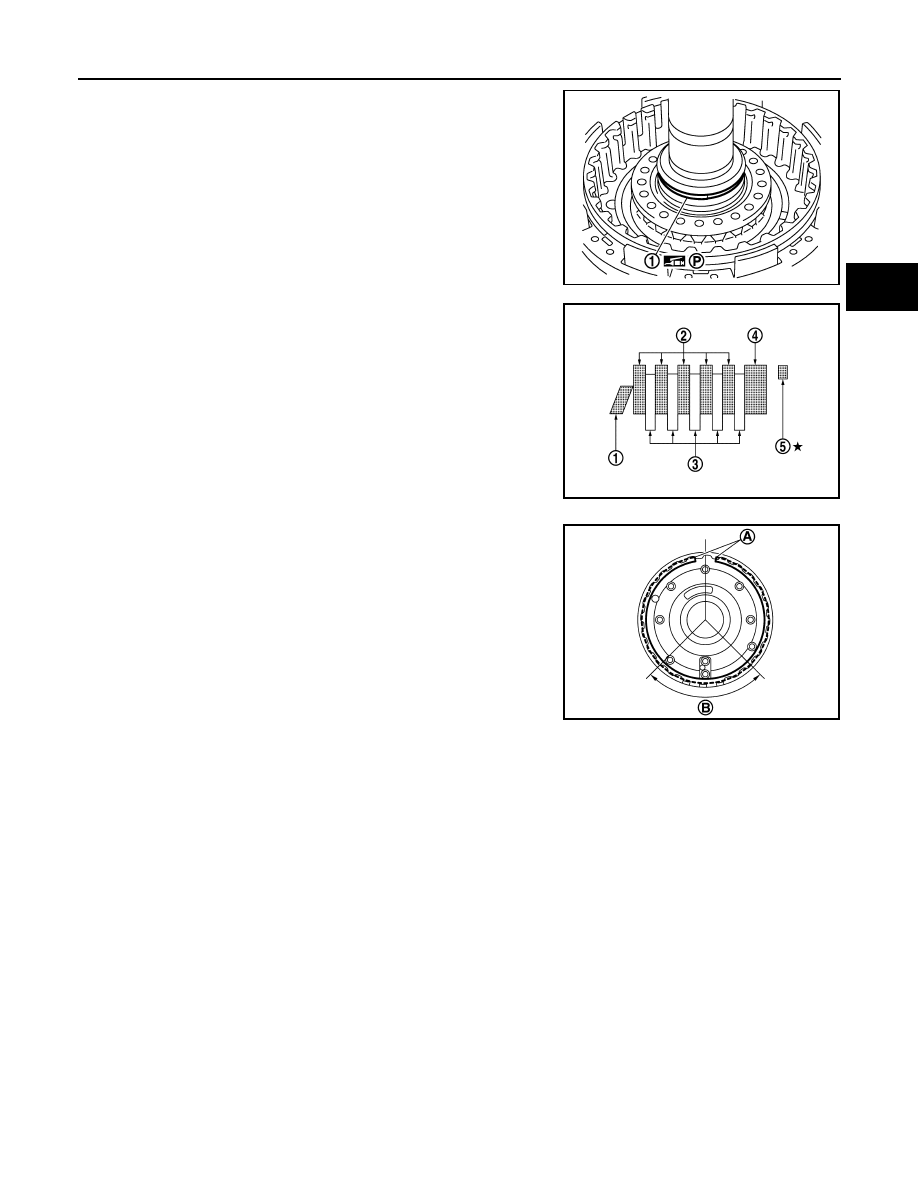
13. Install seal ring (1) to oil pump assembly.

14. Install 2346 brake retaining plate, drive plates, driven plates,

dish plate and snap ring to oil pump assembly.

CAUTION:

• Check the order of plates.

• Never install snap ring mating part (A) to the clearance

groove [(B) shown in the figure] of oil pump cover.

Inspection and Adjustment

INFOID:0000000006226923

INSPECTION AFTER DISASSEMBLY

Each Snap Ring

Check for deformation, fatigue or damage. If necessary, replace snap ring.

Each Spring Retainer

Check for deformation, fatigue or damage. If necessary, replace spring retainer.

2346 Brake Drive Plates

Check facing for burns, cracks or damage. If necessary, replace drive plates and driven plates.

2346 Brake Retaining Plate, Driven Plates and Dish Plate

Check facing for burns, cracks or damage. If necessary, replace retaining plate and dish plate.

INSPECTION AFTER ASSEMBLY

2346 Brake Clearance

JPDIA1092ZZ

1

: Dish plate

2

: Driven plate (five pieces)

3

: Drive plate (five pieces)

4

: Retaining plate

5

:  Snap  ring

JPDIA1153ZZ

JSDIA1724ZZ

TM-278

< UNIT DISASSEMBLY AND ASSEMBLY >

[7AT: RE7R01B]

OIL PUMP, 2346 BRAKE, FRONT BRAKE PISTON

Set a dial indicator (A) as shown in the figure. Blow air into 2346
brake oil pressure hole (B), and measure 2346 brake clearance. If
clearance is outside the specified value, adjust clearance by select-
ing an appropriate snap ring (1). Refer to 

TM-222, "Oil Channel"

.

CAUTION:

Never exceed the specified air pressure value.

Air pressure

: 300kPa (3.06 kg/cm

2

, 43.5 psi)

2346 brake 
clearance

: Refer to 

TM-298, "2346 Brake Clear-

ance"

.

JPDIA1148ZZ

UNDER DRIVE CARRIER, FRONT BRAKE HUB

TM-279

< UNIT DISASSEMBLY AND ASSEMBLY >

[7AT: RE7R01B]

C

E

F

G

H

I

J

K

L

M

A

B

TM

N

O

P

UNDER DRIVE CARRIER, FRONT BRAKE HUB

Exploded View

INFOID:0000000006226924

Disassembly

INFOID:0000000006226925

1.

Remove snap ring (1) from front brake hub using a flat-bladed
screwdriver.

CAUTION:

• Be careful not to scratch front brake hub and under drive

carrier assembly.

• Be careful not to damage snap ring.

2.

Remove under drive carrier assembly (1) from front brake hub.

1.

Snap ring

2.

Under drive carrier assembly

3.

Front brake hub

JPDIA1127ZZ

JPDIA1128ZZ

JPDIA1129ZZ

TM-280

< UNIT DISASSEMBLY AND ASSEMBLY >

[7AT: RE7R01B]

UNDER DRIVE CARRIER, FRONT BRAKE HUB

3.

Remove snap ring (1) from front brake hub using a flat-bladed
screwdriver.

CAUTION:

• Be careful not to scratch front brake hub.
• Be careful not to damage snap ring.

Assembly

INFOID:0000000006226926

1.

Install snap ring (1) to front brake hub.

CAUTION:

Be careful not to damage snap ring.

2.

Install under drive carrier assembly (1) to front brake hub.

3.

Install snap ring (1) to front brake hub using a flat-bladed screw-
driver.

CAUTION:

• Be careful not to scratch front brake hub.
• Be careful not to damage snap ring.

Inspection

INFOID:0000000006226927

INSPECTION AFTER REMOVAL

• Each Snap Ring

Check for deformation, fatigue or damage. If necessary, replace snap ring.

• Under Drive Carrier Assembly

Check for deformation, fatigue or damage. If necessary, replace under drive carrier assembly.

• Front Brake Hub

JPDIA1130ZZ

JPDIA1130ZZ

JPDIA1129ZZ

JPDIA1128ZZ


Content   ..  1340  1341  1342  1343   ..