Content .. 1315 1316 1317 1318 ..
Infiniti QX56 (Z62). Manual - part 1317
A/T SHIFT SELECTOR
TM-177
< REMOVAL AND INSTALLATION >
[7AT: RE7R01B]
C
E
F
G
H
I
J
K
L
M
A
B
TM
N
O
P
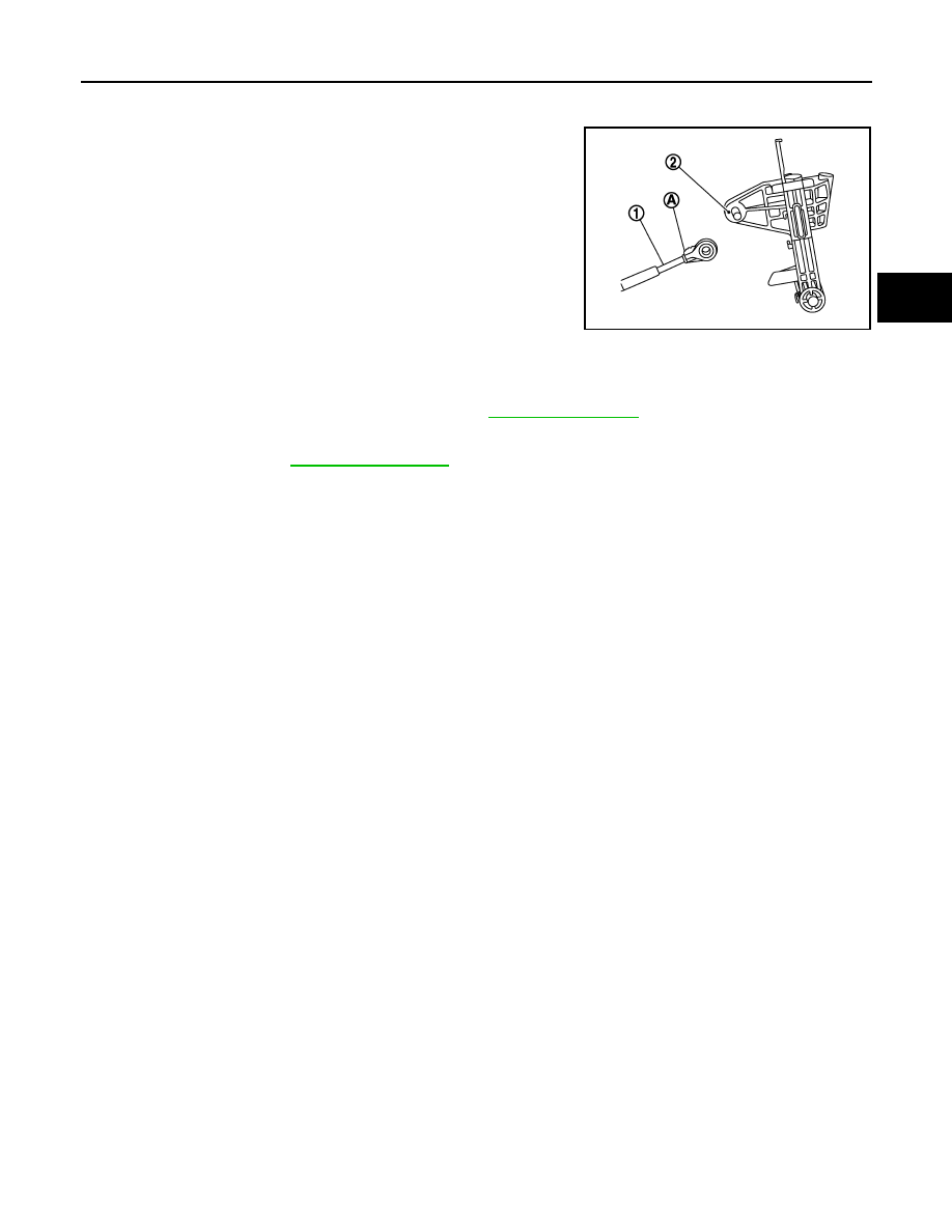
INSTALLATION
Note the following, and install in the reverse order of removal.
• When installing control cable (1) to A/T shift selector assembly (2),
check that control cable is fully pressed in with the ribbed (A) sur-
face facing upward.
• Refer to the followings when installing the selector lever knob to
the A/T shift selector assembly.
1.
Install the lock pin to the selector lever knob.
2.
Insert the shift lever knob into the shift lever until it clicks.
CAUTION:
• Install it straight, and never tap or apply any shock to
install it.
• Never press selector button.
Inspection and Adjustment
INFOID:0000000006226893
INSPECTION AFTER INSTALLATION
Check A/T position after adjusting A/T position. Refer to
.
ADJUSTMENT AFTER INSTALLATION
Adjust A/T position. Refer to
JPDIA0609ZZ