Infiniti QX56 (Z62). Manual - part 1283


  Index      Infiniti     Infiniti QX56 (Z62) - service repair manual 2011 year


Search            


Content   ..  1281  1282  1283  1284   ..


Infiniti QX56 (Z62). Manual - part 1283


STRUCTURE AND OPERATION

TM-41

< SYSTEM DESCRIPTION >

[7AT: RE7R01B]

C

E

F

G

H

I

J

K

L

M

A

B

TM

N

O

P

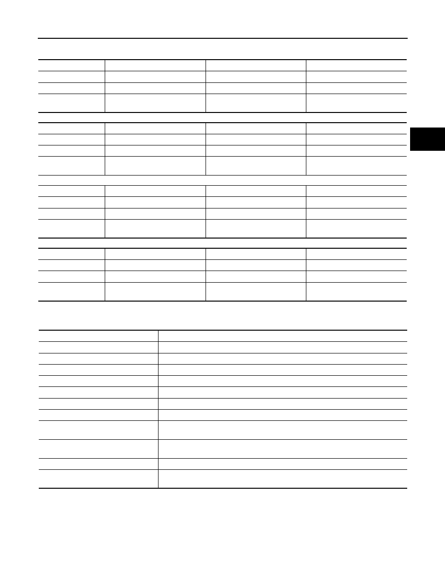
• Each planetary gear enters the state described below.

Front planetary gear

Under drive planetary gear

Rear planetary gear

Mid planetary gear

TRANSMISSION : Component Description

INFOID:0000000006226765

FLUID COOLER & FLUID WARMER SYSTEM

FLUID COOLER & FLUID WARMER SYSTEM : System Description

INFOID:0000000006226766

The A/T fluid temperature is controlled to an appropriate level by the A/T fluid cooler and A/T fluid warmer.

Name

Front sun gear

Front carrier

Front internal gear

Condition

Output

Input

Direction of rotation

Counterclockwise revolution

Clockwise revolution

Clockwise revolution

Number of revolutions

Deceleration from front internal 

gear

Deceleration from front internal 

gear

Same number of revolution as the 

input shaft

Name

Under drive sun gear

Under drive carrier

Under drive internal gear

Condition

Fixed

Input/Output

Direction of rotation

Counterclockwise revolution

Clockwise revolution

Number of revolutions

Acceleration from under drive inter-

nal gear

Same number of revolution as the 

front carrier

Name

Rear sun gear

Rear carrier

Rear internal gear

Condition

Output

Fixed

Input

Direction of rotation

Counterclockwise revolution

Clockwise revolution

Number of revolutions

Acceleration from rear internal 

gear

Same number of revolution as the 

under drive internal gear

Name

Mid sun gear

Mid carrier

Mid internal gear

Condition

Input

Output

Fixed

Direction of rotation

Counterclockwise revolution

Counterclockwise revolution

Number of revolutions

Same number of revolution as the 

rear sun gear

Deceleration from mid sun gear

Name of the Part (Abbreviation)

Function

Front brake (FR/B)

Fastens the under drive carrier.

Input clutch (I/C)

Connects the input shaft, the mid internal gear and the rear carrier.

Direct clutch (D/C)

Connects the rear carrier and the rear sun gear.

High and low reverse clutch (HLR/C)

Connects the rear sun gear and the mid sun gear.

Reverse brake (R/B)

Fastens the rear carrier.

Low brake (L/B)

Fastens the mid sun gear.

2346 brake (2346/B)

Fastens the under drive sun gear.

1st one-way clutch (1st OWC)

Allows the under drive carrier to turn freely in the forward direction but fastens it for reverse 
rotation.

2nd one-way clutch (2nd OWC)

Allows the rear sun gear to turn freely in the forward direction but fastens it for reverse ro-
tation.

Torque converter

Amplifies driving force the engine, and transmits it to transmission input shaft.

Oil pump

Driven by the engine, oil pump supplies oil to torque converter, control valve assembly, and 
each lubricating system.

TM-42

< SYSTEM DESCRIPTION >

[7AT: RE7R01B]

STRUCTURE AND OPERATION

A/T FLUID COOLER SCHEMATIC

COMPONENT DESCRIPTION

A/T fluid warmer

• The A/T fluid warmer (1) is installed on the front part of cylinder

block of engine.

• When engine is started while engine and A/T are cold, engine cool-

ant temperature rises more quickly than A/T fluid temperature. A/T
fluid warmer is provided with two circuits for ATF and engine cool-
ant respectively so that warmed engine coolant warms ATF
quickly. This helps shorten A/T warming up time, improving fuel
economy.

• A cooling effect is obtained when A/T fluid temperature is high.

A/T fluid cooler (with bypass valve)

• A/T fluid cooler (1) is installed in the front of radiator (2) and con-

denser (3).

• A/T fluid cooler is provided with a bypass valve that controls ATF

flow. Bypass valve operates by thermo wax and a return spring.
Bypass valve fully opens when A/T fluid temperature is approxi-
mately 90

°

C (194

°

F) and fully closes when A/T fluid temperature is

approximately 100

°

C (212

°

F).

• When A/T fluid temperature is low, the bypass valve is open. Most

of ATF therefore returns to the transmission without flowing into the
cooler core that has larger flow resistance.

JSDIA1803GB

JSDIA1811ZZ

JSDIA1814ZZ

JSDIA1815GB

STRUCTURE AND OPERATION

TM-43

< SYSTEM DESCRIPTION >

[7AT: RE7R01B]

C

E

F

G

H

I

J

K

L

M

A

B

TM

N

O

P

• When A/T fluid temperature rises [to approximately 100

°

C

(212

°

F)], bypass valve closes and allows ATF to flow into cooler

core. ATF flowing into cooler core is cooled by air stream caused
by vehicle travel and returned to transmission.

JSDIA1816GB

TM-44

< SYSTEM DESCRIPTION >

[7AT: RE7R01B]

SYSTEM

SYSTEM

A/T CONTROL SYSTEM

A/T CONTROL SYSTEM : System Diagram

INFOID:0000000006226767

A/T CONTROL SYSTEM : System Description

INFOID:0000000006226768

INPUT/OUTPUT SIGNAL CHART

SYSTEM DESCRIPTION

• The A/T senses vehicle operating conditions through various sensors or signals. It always controls the opti-

mum shift position and reduces shifting and lock-up shocks.

• Receive input signals transmitted from various switches and sensors.
• Determine required line pressure, shifting point, lock-up operation, etc.

JSDIA1853GB

Sensor (or signal)

TCM function

Actuator

Transmission range switch
Accelerator pedal position signal
Closed throttle position signal
Wide open throttle position signal
Engine speed signal
A/T fluid temperature sensor
Output speed sensor
Vehicle speed signal
Manual mode switch signal
Stop lamp switch signal
Input speed sensor 1, 2
Yaw rate/side/decel G sensor
Tow mode switch signal

Line pressure control (

TM-48

)

Shift change control (

TM-50

)

Shift pattern control (

TM-54

)

Lock-up control (

TM-56

)

Fail-safe control (

TM-45

)

Self-diagnosis (

TM-61

)

CONSULT-III communication line (

TM-61

)

CAN communication line (

TM-103

)

Input clutch solenoid valve 
Direct clutch solenoid valve 
Front brake solenoid valve
High and low reverse clutch solenoid valve
Low brake solenoid valve
Torque converter clutch solenoid valve
Line pressure solenoid valve
Anti-interlock solenoid valve
2346 brake solenoid valve
A/T CHECK indicator lamp
Tow mode indicator lamp
Shift position indicator
Back-up lamp relay
Starter relay


Content   ..  1281  1282  1283  1284   ..