Content .. 1254 1255 1256 1257 ..
Infiniti QX56 (Z62). Manual - part 1256
ST-34
< REMOVAL AND INSTALLATION >
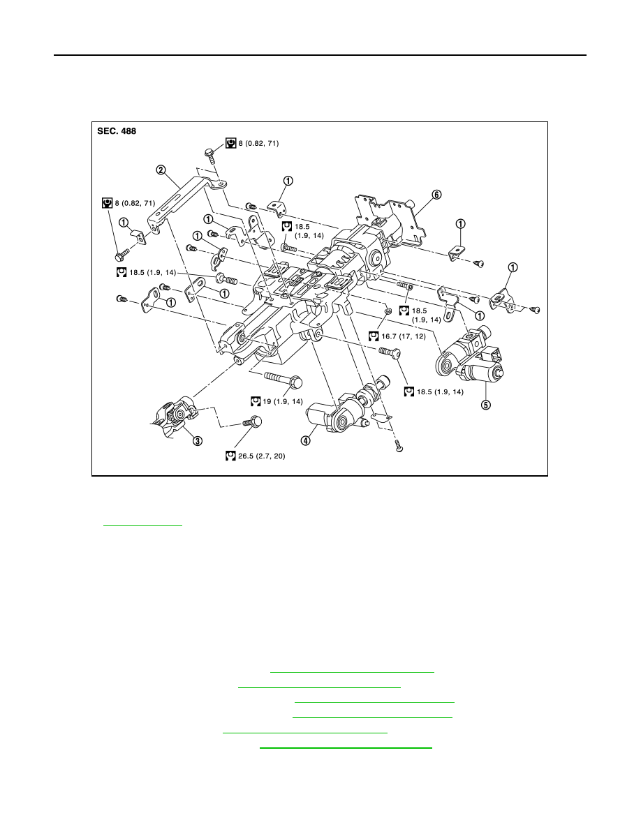
STEERING COLUMN
STEERING COLUMN
Exploded View
INFOID:0000000006225601
Removal and Installation
INFOID:0000000006225602
REMOVAL
CAUTION:
• Never give axial impact to steering column assembly during removal.
• Never move steering gear assembly when removing steering column assembly.
• Never rotate the steering shaft when removing steering column assembly.
1.
Set the vehicle to the straight-ahead position.
2.
Place the tilt to the highest level. Place the telescopic to the longest level.
3.
Remove driver air bag module. Refer to
SR-11, "Removal and Installation"
.
4.
Remove steering wheel. Refer to
ST-33, "Removal and Installation"
.
5.
Remove instrument lower panel LH. Refer to
IP-14, "Removal and Installation"
.
6.
Remove the steering column cover. Refer to
IP-14, "Removal and Installation"
7.
Remove spiral cable. Refer to
SR-14, "Removal and Installation"
.
8.
Remove combination switch. Refer to
BCS-82, "Removal and Installation"
9.
Disconnect each switch harness connectors installed to steering column assembly.
10. Remove the upper joint mounting bolt and separate the joint from upper joint.
11. Remove steering column assembly.
1.
Bracket
2.
Steering column mounting bracket
3.
Upper joint
4.
Telescopic motor
5.
Tilt motor
6.
Steering column assembly
Refer to
for symbols in the figure.
JPGIA0066GB