Infiniti QX56 (Z62). Manual - part 119


  Index      Infiniti     Infiniti QX56 (Z62) - service repair manual 2011 year


Search            


Content   ..  117  118  119  120   ..


Infiniti QX56 (Z62). Manual - part 119


BR-8

< PERIODIC MAINTENANCE >

BRAKE PEDAL

Brake Pedal Height

1.

Remove instrument lower panel LH. Refer to 

IP-14, "Removal and Installation"

.

2.

Disconnect the stop lamp switch harness connector and the brake switch harness connector.

3.

Loosen the stop lamp switch and brake switch by turning it 45

°

 counterclockwise.

4.

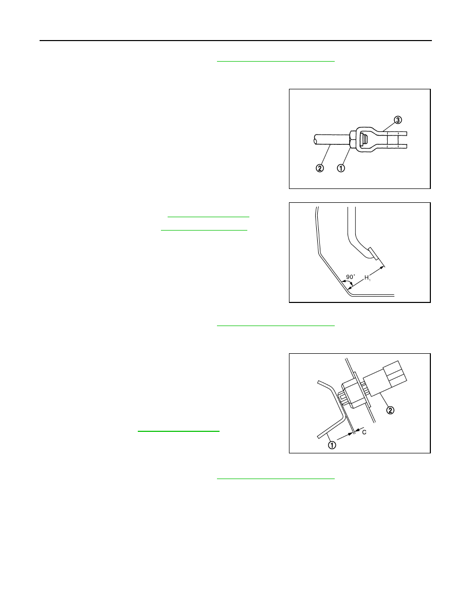
Loosen the input rod lock nut (1).

5.

Rotate the input rod (2), and adjust the brake pedal to the speci-
fied height.

CAUTION:

• Perform it with the floor trim removed.
• The threaded end of the input rod must project to the

inner side of the clevis (3).

6.

Tighten the lock nut. Refer to 

BR-28, "Exploded View"

.

7.

Adjust the clearance between the brake pedal bracket and the
stop lamp switch and brake switch threaded end after adjusting
the brake pedal height.

Stop Lamp Switch and Brake Switch

1.

Remove instrument lower panel LH. Refer to 

IP-14, "Removal and Installation"

.

2.

Disconnect the stop lamp switch harness connector and the brake switch harness connector.

3.

Loosen the stop lamp switch and brake switch by turning it 45

°

 counterclockwise.

4.

Press-fit the stop lamp switch and brake switch (2) until the stop
lamp switch and brake switch hits the brake pedal bracket (1)
45

°

 clockwise while pulling the brake pedal pad slightly.

CAUTION:

• The clearance (C) between the brake pedal bracket and

stop lamp switch and brake switch threaded end and
must be the specified value.

• The stop lamp must turn off when the brake pedal is

released.

Brake Pedal Play

1.

Remove instrument lower panel LH. Refer to 

IP-14, "Removal and Installation"

.

2.

Disconnect the stop lamp switch harness connector and the brake switch harness connector.

3.

Loosen the stop lamp switch and brake switch by turning it 45

°

 counterclockwise.

JPFIA0662ZZ

H

1

: Refer to 

BR-47, "Brake Pedal"

.

JPFIA0279ZZ

C

: Refer to 

BR-47, "Brake Pedal"

.

JPFIA0674ZZ

BRAKE PEDAL

BR-9

< PERIODIC MAINTENANCE >

C

D

E

G

H

I

J

K

L

M

A

B

BR

N

O

P

4.

Press-fit the stop lamp switch and brake switch (2) until the stop
lamp switch and brake switch hits the brake pedal bracket (1)
45

°

 clockwise while pulling the brake pedal pad slightly.

CAUTION:

• The clearance (C) between the brake pedal bracket and

stop lamp switch and brake switch threaded end and
must be the specified value.

• The stop lamp must turn off when the brake pedal is

released.

Depressed Brake Pedal Height

1.

Perform the air bleeding. Refer to 

BR-11, "Bleeding Brake System"

.

2.

Check the height between the dash lower panel (1) and the top
face of the brake pedal (H

2

) when depressing the brake pedal

with a force of 490 N (50 kg, 110 lb) while the engine is running.

CAUTION:

Perform it with the floor trim removed.

3.

Adjust the brake pedal play after adjusting the brake pedal
height, clearance between the brake pedal bracket and the stop
lamp switch and brake switch threaded end.

C

: Refer to 

BR-47, "Brake Pedal"

.

JPFIA0674ZZ

H

2

: Refer to 

BR-47, "Brake Pedal"

.

JPFIA0068ZZ

BR-10

< PERIODIC MAINTENANCE >

BRAKE FLUID

BRAKE FLUID

Inspection

INFOID:0000000006222463

BRAKE FLUID LEVEL

• Check that the fluid level in the reservoir tank is within the specified range (MAX – MIN lines).

CAUTION:

Turn OFF the ignition switch and depress the brake pedal 20 times or more to check brake fluid level.
NOTE:
Since brake fluid is in the accumulator in pressurized condition, the reservoir tank brake fluid level should be
lower than the MAX line.

• Visually check for any brake fluid leakage around the reservoir tank.
• Check the brake system for any leakage if the fluid level is extremely low (lower than MIN).
• Check the brake system for fluid leakage if the warning lamp remains illuminated even after the parking

brake is released.

• Check the reservoir tank for the mixing of foreign matter (e.g. dust) and oils other than brake fluid.

BRAKE LINE

1.

Check brake line (tubes and hoses) for cracks, deterioration or other damage. Replace any damaged
parts.

2.

Depress the brake pedal with a force of 490 N (50 kg, 110 lb)
and hold down the pedal for approx. 5 seconds with the engine
running. Check for any fluid leakage.

CAUTION:

Retighten the applicable connection to the specified torque
and repair any abnormal (damaged, worn or deformed) part
if any brake fluid leakage is present.

Draining

INFOID:0000000006222464

FRONT BRAKE

CAUTION:

• If the brake fluid adheres to the brake caliper assembly and disc rotor, quickly wipe it off.
• Never spill or splash brake fluid on painted surfaces. Brake fluid may seriously damage paint. Wipe it

off immediately and wash with water if it gets on a painted surface.

• Never operate the brake pedal with the reservoir cap removed. Failure to do this may cause the scat-

tering of brake fluid.

• Never operate the brake pedal excessively during the work procedure.

1.

Turn the ignition switch ON.

2.

Connect a vinyl tube to the bleed valve.

3.

Depress the brake pedal and loosen the bleeder valve.

4.

Depress the brake pedal several time gradually discharge brake fluid.

REAR BRAKE

CAUTION:

• If the brake fluid adheres to the brake caliper assembly and disc rotor, quickly wipe it off.
• Never spill or splash brake fluid on painted surfaces. Brake fluid may seriously damage paint. Wipe it

off immediately and wash with water if it gets on a painted surface.

• Never operate the brake pedal with the reservoir cap removed. Failure to do this may cause the scat-

tering of brake fluid.

• Never operate the brake pedal excessively during the work procedure.

1.

Turn the ignition switch ON.

2.

Connect a vinyl tube to the bleed valve.

3.

Depress the brake pedal and loosen the bleeder valve to gradually discharge brake fluid.

SBR389C

BRAKE FLUID

BR-11

< PERIODIC MAINTENANCE >

C

D

E

G

H

I

J

K

L

M

A

B

BR

N

O

P

NOTE:
Since brake fluid is conveyed by the motor, the brake pedal is not necessarily depressed.

Refilling

INFOID:0000000006222465

FRONT BRAKE

CAUTION:

• If the brake fluid adheres to the brake caliper assembly and disc rotor, quickly wipe it off.
• Never spill or splash brake fluid on painted surfaces. Brake fluid may seriously damage paint. Wipe it

off immediately and wash with water if it gets on a painted surface.

• Never operate the brake pedal with the reservoir cap removed. Failure to do this may cause the scat-

tering of brake fluid.

• Never operate the brake pedal excessively during the work procedure.
• Monitor the fluid level in the reservoir tank while performing the refilling.
1.

Check that there is no foreign material in the reservoir tank, and refill with new brake fluid.

CAUTION:

• Never reuse drained brake fluid.
• Never allow oils other than brake fluid to enter the reservoir tank.

2.

Turn the ignition switch ON.

3.

Connect a vinyl tube to the bleed valve.

4.

Depress the brake pedal and loosen the bleeder valve.

5.

Depress the brake pedal several times until the refilled brake fluid is discharged and tighten the air
bleeder to the specified torque with the brake pedal depressed. Refer to 

BR-36, "BRAKE CALIPER

ASSEMBLY : Exploded View"

.

6.

Perform the air bleeding. Refer to 

BR-11, "Bleeding Brake System"

.

REAR BRAKE

CAUTION:

• If the brake fluid adheres to the brake caliper assembly and disc rotor, quickly wipe it off.
• Never spill or splash brake fluid on painted surfaces. Brake fluid may seriously damage paint. Wipe it

off immediately and wash with water if it gets on a painted surface.

• Never operate the brake pedal with the reservoir cap removed. Failure to do this may cause the scat-

tering of brake fluid.

• Never operate the brake pedal excessively during the work procedure.
• Monitor the fluid level in the reservoir tank while performing the refilling.

1.

Check that there is no foreign material in the reservoir tank, and refill with new brake fluid.

CAUTION:

• Never reuse drained brake fluid.
• Never allow oils other than brake fluid to enter the reservoir tank.

2.

Turn the ignition switch ON.

3.

Connect a vinyl tube to the bleed valve.

4.

Depress the brake pedal and loosen the bleeder valve.

5.

Depress the brake pedal several times until the refilled brake fluid is discharged and tighten the air
bleeder to the specified torque with the brake pedal depressed. Refer to 

BR-42, "BRAKE CALIPER

ASSEMBLY : Exploded View"

.

NOTE:
Since brake fluid is conveyed by the motor, the brake pedal is not necessarily depressed.

6.

Perform the air bleeding. Refer to 

BR-11, "Bleeding Brake System"

.

Bleeding Brake System

INFOID:0000000006222466

CAUTION:

• Bleed air in the following order: motor/accumulator assembly 

 front right brake 

 front left brake

 rear left brake 

 and rear right brake.

• The VDC warning lamp, ABS warning lamp and brake warning lamp turn ON and DTC “C118E” may

be detected in self-diagnosis result for “ABS” with CONSULT-III when the brake pedal is excessively
operated, such as air bleeding. This is not a system malfunction because this occurs due to the tem-
porary decrease in accumulator fluid pressure. The system returns to normal condition when the
accumulator fluid pressure reaches the specified pressure with the ignition switch ON and the VDC


Content   ..  117  118  119  120   ..