Infiniti QX56 (Z62). Manual - part 1189


  Index      Infiniti     Infiniti QX56 (Z62) - service repair manual 2011 year


Search            


Content   ..  1187  1188  1189  1190   ..


Infiniti QX56 (Z62). Manual - part 1189


SEC-146

< DTC/CIRCUIT DIAGNOSIS >

[WITH INTELLIGENT KEY SYSTEM]

SECURITY INDICATOR LAMP

SECURITY INDICATOR LAMP

Component Function Check

INFOID:0000000006226312

1.

CHECK FUNCTION

1.

Perform “THEFT IND” in “ACTIVE TEST” mode of “IMMU” of “BCM” using CONSULT-III.

2.

Check security indicator lamp operation.

Is the inspection result normal?

YES

>> INSPECTION END

NO

>> Go to 

SEC-146, "Diagnosis Procedure"

.

Diagnosis Procedure

INFOID:0000000006226313

1.

CHECK SECURITY INDICATOR LAMP POWER SUPPLY CIRCUIT

1.

Turn ignition switch OFF.

2.

Disconnect combination meter connector.

3.

Check voltage between combination meter harness connector and ground.

Is the inspection result normal?

YES

>> GO TO 2.

NO-1

>> Check 10 A fuse [No. 11, located in the fuse block (J/B)].

NO-2

>> Check harness for open or short between combination meter and fuse.

2.

CHECK SECURITY INDICATOR LAMP SIGNAL

1.

Connect combination meter connector.

2.

Disconnect BCM connector.

3.

Check voltage between BCM harness connector and ground.

Is the inspection result normal?

YES

>> GO TO 3.

NO

>> GO TO 4.

3.

REPLACE BCM

1.

Replace BCM. Refer to 

BCS-81, "Removal and Installation"

.

2.

Perform initialization of BCM and registration of all Intelligent Keys using CONSULT-III.
For initialization and registration procedures, refer to CONSULT-III Operation Manual NATS-IVIS/NVIS.

>> INSPECTION END

4.

CHECK SECURITY INDICATOR LAMP CIRCUIT

1.

Disconnect combination meter connector.

2.

Check continuity between combination meter harness connector and BCM harness connector.
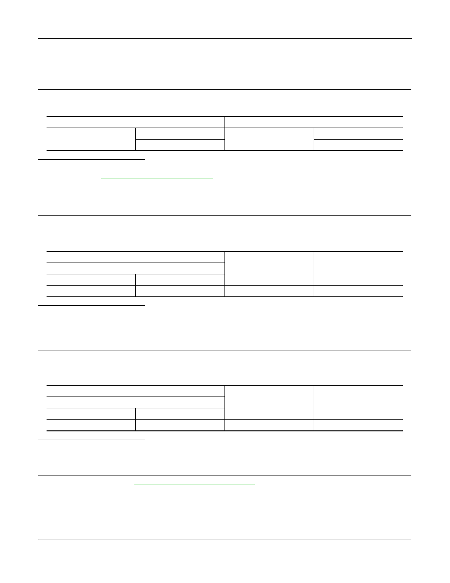
Test item

Description

THEFT IND

ON

Security indicator lamp

Illuminates

OFF

Does not illuminate

(+)

(–)

Voltage (V)

(Approx.)

Combination meter

Connector

Terminal

M34

1

Ground

Battery voltage

(+)

(–)

Voltage (V)

(Approx.)

BCM

Connector

Terminal

M68

23

Ground

Battery voltage

SECURITY INDICATOR LAMP

SEC-147

< DTC/CIRCUIT DIAGNOSIS >

[WITH INTELLIGENT KEY SYSTEM]

C

D

E

F

G

H

I

J

L

M

A

B

SEC

N

O

P

3.

Check continuity between combination meter harness connector and ground.

Is the inspection result normal?

YES

>> Replace combination meter. Refer to 

MWI-85, "Removal and Installation"

.

NO

>> Repair or replace harness.

Combination meter

BCM

Continuity

Connector

Terminal

Connector

Terminal

M34

28

M68

23

Existed

Combination meter

Ground

Continuity

Connector

Terminal

M34

28

Not existed

SEC-148

< SYMPTOM DIAGNOSIS >

[WITH INTELLIGENT KEY SYSTEM]

ENGINE DOES NOT START WHEN INTELLIGENT KEY IS INSIDE OF VEHICLE

SYMPTOM DIAGNOSIS

ENGINE DOES NOT START WHEN INTELLIGENT KEY IS INSIDE OF VE-
HICLE

Description

INFOID:0000000006226323

Engine does not start when push-button ignition switch is pressed while carrying Intelligent Key.
NOTE:
• Check that vehicle is under the condition shown in “Conditions of vehicle” before starting diagnosis, and

check each symptom.

• The engine start function, door lock function, power distribution system, and NATS-IVIS/NVIS in the Intelli-

gent Key system are closely related to each other regarding control. The vehicle security function can oper-
ate only when the door lock and power distribution system are operating normally.

Conditions of Vehicle (Operating Conditions)

• “ENGINE START BY I-KEY” in “WORK SUPPORT” is ON when setting on CONSULT-III.
• Intelligent Key is not inserted in key slot.
• One or more of Intelligent Keys with registered Intelligent Key ID is in the vehicle.

Diagnosis Procedure

INFOID:0000000006226324

1.

PERFORM WORK SUPPORT

Perform “INSIDE ANT DIAGNOSIS” on Work Support in “INTELLIGENT KEY”.
Refer to 

SEC-22, "INTELLIGENT KEY : CONSULT-III Function (BCM - INTELLIGENT KEY)"

.

>> GO TO 2.

2.

PERFORM SELF-DIAGNOSIS RESULT

Perform Self-Diagnosis Result in “BCM”, and check whether or not DTC of inside key antenna is detected.

Is DTC detected?

YES

>> Refer to 

BCS-57, "DTC Index"

.

NO

>> GO TO 3.

3.

CHECK PUSH-BUTTON IGNITION SWITCH

Check push-button ignition switch.
Refer to 

PCS-71, "Component Function Check"

.

Is the operation normal?

YES

>> GO TO 4.

NO

>> Repair or replace malfunctioning parts.

4.

CONFIRM THE OPERATION

Confirm the operation again.
Is the inspection normal?

YES

>> Check intermittent incident. Refer to 

GI-40, "Intermittent Incident"

.

NO

>> GO TO 1.

STEERING DOES NOT LOCK

SEC-149

< SYMPTOM DIAGNOSIS >

[WITH INTELLIGENT KEY SYSTEM]

C

D

E

F

G

H

I

J

L

M

A

B

SEC

N

O

P

STEERING DOES NOT LOCK

Description

INFOID:0000000006226325

Steering does not lock when door is open while ignition switch is OFF.
NOTE:
Before performing the diagnosis, check “Work Flow”. Refer to 

SEC-48, "Work Flow"

.

Diagnosis Procedure

INFOID:0000000006226326

1.

CHECK DOOR SWITCH

Check door switch.
Refer to 

DLK-117, "Component Function Check"

.

Is the inspection normal?

YES

>> GO TO 2.

NO

>> Repair or replace malfunctioning parts.

2.

CONFIRM THE OPERATION

Confirm the operation again.

Is the inspection normal?

YES

>> Check intermittent incident. Refer to 

GI-40, "Intermittent Incident"

.

NO

>> GO TO 1.


Content   ..  1187  1188  1189  1190   ..