Infiniti QX56 (Z62). Manual - part 118


  Index      Infiniti     Infiniti QX56 (Z62) - service repair manual 2011 year


Search            


Content   ..  116  117  118  119   ..


Infiniti QX56 (Z62). Manual - part 118


BR-4

< PRECAUTION >

PRECAUTIONS

5.

When the repair work is completed, re-connect both battery cables. With the brake pedal released, turn
the push-button ignition switch from ACC position to ON position, then to LOCK position. (The steering
wheel will lock when the push-button ignition switch is turned to LOCK position.)

6.

Perform self-diagnosis check of all control units using CONSULT-III.

Precaution for Procedure without Cowl Top Cover

INFOID:0000000006228173

When performing the procedure after removing cowl top cover, cover
the lower end of windshield with urethane, etc.

Precaution for Brake system

INFOID:0000000006222459

WARNING:

Clean any dust from the front brake and rear brake with a vacuum dust collector. Never blow with com-
pressed air.
• Brake fluid use refer to 

MA-10, "Fluids and Lubricants"

.

• Never reuse drained brake fluid.
• Never spill or splash brake fluid on painted surfaces. Brake fluid may seriously damage paint. Wipe it off

immediately and wash with water if it gets on a painted surface.

• Always confirm the specified tightening torque when installing the brake pipes.
• After pressing the brake pedal more deeply or harder than normal driving, such as air bleeding, check each

item of brake pedal. Adjust brake pedal if it is outside the standard value.

• Always clean with new brake fluid when cleaning the brake caliper and other components.
• Never use mineral oils such as gasoline or light oil to clean. They may damage rubber parts and cause

improper operation.

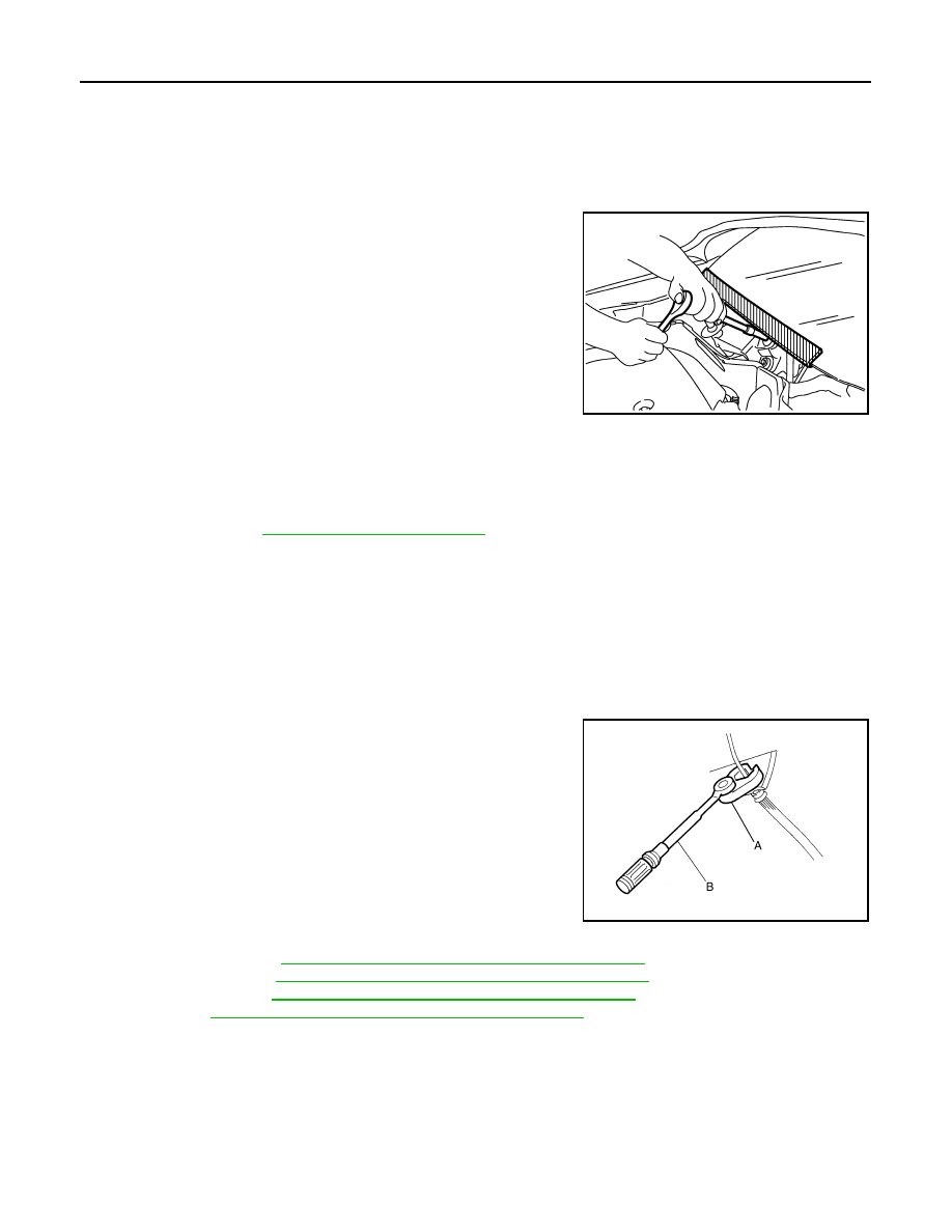
• Always loosen the brake tube flare nut with a flare nut wrench.
• Tighten the brake tube flare nut to the specified torque with a crow-

foot (A) and torque wrench (B).

• Brake system is an important safety part. If a brake fluid leak is

detected, always disassemble the affected part. If a malfunction is
detected, replace part with a new one.

• Always connect the battery terminals when moving the vehicle.
• Turn the ignition switch OFF and disconnect the hydraulic booster

assembly harness connector or the battery negative terminal
before performing the work.

• Check that no brake fluid leakage is present after replacing the

parts.

• Burnish the brake contact surfaces after refinishing or replacing

rotors, after replacing pads, or if a soft pedal occurs at very low mileage.

- Front brake pad: Refer to 

BR-16, "BRAKE PAD : Inspection and Adjustment"

.

- Front disc rotor: Refer to 

BR-16, "DISC ROTOR : Inspection and Adjustment"

.

- Rear brake pad: refer to 

BR-18, "BRAKE PAD : Inspection and Adjustment"

.

- Rear disc rotor: 

BR-18, "DISC ROTOR : Inspection and Adjustment"

.

PIIB3706J

JPFIA0001ZZ

PREPARATION

BR-5

< PREPARATION >

C

D

E

G

H

I

J

K

L

M

A

B

BR

N

O

P

PREPARATION

PREPARATION

Commercial Service Tools

INFOID:0000000006222460

Tool name

Description

Power tool

Loosening bolts and nuts

Pin punch
a: 4 mm (0.16 in)

Removing and installing reservoir tank

Brake caliper wrench

Return the piston

PBIC0190E

NT410

NNFIA0040ZZ

BR-6

< SYMPTOM DIAGNOSIS >

NOISE, VIBRATION AND HARSHNESS (NVH) TROUBLESHOOTING

SYMPTOM DIAGNOSIS

NOISE, VIBRATION AND HARSHNESS (NVH) TROUBLESHOOTING

NVH Troubleshooting Chart

INFOID:0000000006222461

Use the chart below to find the cause of the symptom. If necessary, repair or replace these parts.

×

: Applicable

Reference page

BR-16

BR-18

BR-16

BR-18

BR-36

BR-42

BR-16

BR-18

BR-16

BR-18

BR-16

BR-18

BR-16

BR-18

BR-16

BR-18

BR-16

BR-18

BR-16

BR-18

NV

in

 P

B

 s

e

c

ti

o

n

NV

in

 D

L

N

 s

e

c

ti

o

n

N

H

in DLN section

NV

in

 F

A

X

, R

A

X

 a

nd

 FS

U,

 R

S

U

 s

ec

tio

n

NV

in

 WT s

e

cti

on

NV

in

 WT s

e

cti

on

NV

in

 F

A

X

, R

A

X

 s

e

cti

o

n

NV

in

 S

T

 s

e

c

ti

o

n

Possible cause and
SUSPECTED PARTS

Pad

s

 da

ma

ge

d

Pad

s

 un

ev

en

 wea

r

Sh

im

s da

ma

ge

d

Roto

r im

b

a

la

nc

e

Ro

to

r da

ma

ge

Rotor runout

Roto

r d

e

fo

rma

tio

n

Roto

r d

e

fl

ectio

n

Rotor rust

Roto

r th

ickn

ess 

va

ria

tio

n

Drum

 ou

t o

f ro

un

d

PROPELLER SHAF

T

DIFFE

R

E

NTIAL

AXLE AND SUSPE

NSION

TIRE

ROA

D

 WHEEL

D

R

IV

E

 SH

AF

T

STEERI

N

G

Symptom

BRAKE

Noise

×

×

×

×

×

×

×

×

×

×

Shake

×

×

×

×

×

×

×

Shimmy, Judder

×

×

×

×

×

×

×

×

×

×

×

BRAKE PEDAL

BR-7

< PERIODIC MAINTENANCE >

C

D

E

G

H

I

J

K

L

M

A

B

BR

N

O

P

PERIODIC MAINTENANCE

BRAKE PEDAL

Inspection and Adjustment

INFOID:0000000006222462

INSPECTION

Brake Pedal Height

Check the brake pedal height (H

1

) between the dash lower panel (1)

and the brake pedal upper surface.

CAUTION:

Perform it with the floor trim removed.

Stop Lamp Switch and Brake Switch

Check the clearance (C) between the brake pedal bracket (1) and
the stop lamp switch and brake switch (2) threaded end.

CAUTION:

The stop lamp must turn off when the brake pedal is released.
NOTE:
Pull the brake pedal pad to make the clearance between the stop
lamp switch and brake switch threaded end and the brake pedal
bracket.

Brake Pedal Play

Press the brake pedal. Check the brake pedal play (A) (stroke until
fluid pressure occurs).

Depressed Brake Pedal Height

Check the height between the dash lower panel (1) and the top face
of the brake pedal (H

2

) when depressing the brake pedal with a force

of 490 N (50 kg, 110 lb) while the engine is running.

CAUTION:

Perform it with the floor trim removed.

ADJUSTMENT

H

1

: Refer to 

BR-47, "Brake Pedal"

.

JPFIA0065ZZ

C

: Refer to 

BR-47, "Brake Pedal"

.

JPFIA0674ZZ

A

: Refer to 

BR-47, "Brake Pedal"

.

JPFIA0277ZZ

H

2

: Refer to 

BR-47, "Brake Pedal"

.

JPFIA0068ZZ


Content   ..  116  117  118  119   ..