Infiniti QX56 (Z62). Manual - part 117
BCS-82
< REMOVAL AND INSTALLATION >
COMBINATION SWITCH
COMBINATION SWITCH
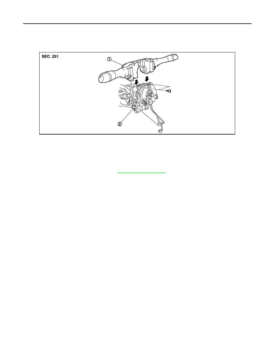
Exploded View
INFOID:0000000006274846
Removal and Installation
INFOID:0000000006274847
REMOVAL
1.
Remove steering column cover. Refer to
.
2.
Remove screws.
3.
Disconnect the connector.
4.
Pull up the combination switch to remove it.
INSTALLATION
Install in the reverse order of removal.
1.
Combination switch
2.
Combination switch connector
JMMIA0328ZZ