Infiniti QX56 (Z62). Manual - part 1043


  Index      Infiniti     Infiniti QX56 (Z62) - service repair manual 2011 year


Search            


Content   ..  1041  1042  1043  1044   ..


Infiniti QX56 (Z62). Manual - part 1043


PWO-10

< REMOVAL AND INSTALLATION >

[POWER SOCKET]

POWER SOCKET

REMOVAL AND INSTALLATION

POWER SOCKET

FRONT POWER SOCKET

FRONT POWER SOCKET : Exploded View

INFOID:0000000006023319

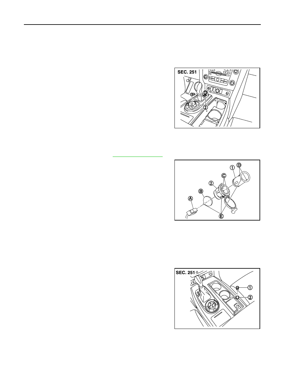
FRONT POWER SOCKET : Removal and Installation

INFOID:0000000006023320

REMOVAL

1.

Remove cluster lid C lower. Refer to 

IP-13, "Exploded View"

.

2.

Disconnect power socket connector (A).

3.

Pull out inner socket (1) by pushing the ring pawl (C) from the
inner socket hole (square) (D).

4.

Remove ring (2) from cluster lid C lower while pressing pawls.

INSTALLATION

Install in the reverse order of removal.   
NOTE:
Align the cut outs of inner socket, ring and cluster lid C lower.

CONSOLE POWER SOCKET (CUP HOLDER)

CONSOLE POWER SOCKET (CUP HOLDER) : Exploded View

INFOID:0000000006023317

CONSOLE POWER SOCKET (CUP HOLDER) : Removal and Installation

INFOID:0000000006023318

REMOVAL

1

: Inner socket

2

:  Ring

JSMIA0262ZZ

B

: Hole for power socket
(Cluster lid C lower)

E

: Cut out

JSMIA0284ZZ

1

: Inner socket

2

:  Ring

JSMIA0372ZZ

PWO

POWER SOCKET

PWO-11

< REMOVAL AND INSTALLATION >

[POWER SOCKET]

C

D

E

F

G

H

I

J

K

L

B

A

O

P

N

1.

Remove console finisher assembly. Refer to 

IP-23, "Exploded View"

.

2.

Disconnect power socket connector and remove power socket illumination bulb.

3.

Pull out inner socket (1) by pushing the ring pawl (B) from the
inner socket hole (square) (C).

4.

Remove ring (2) from console finisher assembly while pressing
pawls.

INSTALLATION

Install in the reverse order of removal.
NOTE:
Align the cut outs of inner socket, ring and console finisher assembly.

CONSOLE POWER SOCKET (REAR)

CONSOLE POWER SOCKET (REAR) : Exploded View

INFOID:0000000006023321

CONSOLE POWER SOCKET (REAR) : Removal and Installation

INFOID:0000000006023322

REMOVAL

1.

Remove console rear finisher. Refer to 

IP-23, "Exploded View"

.

2.

Disconnect power socket connector (A).

3.

Pull out inner socket (1) by pushing the ring pawl (C) from the
inner socket hole (square) (D).

4.

Remove ring (2) from console rear finisher while pressing pawls.

INSTALLATION

Install in the reverse order of removal.   
NOTE:
Align the cut outs of inner socket, ring and console rear finisher.

LUGGAGE ROOM POWER SOCKET

A

: Hole for power socket
(Console finisher assembly)

D

: Cut out

JSMIA0373ZZ

1

: Inner socket

2

:  Ring

JSMIA0263ZZ

B

: Hole for power socket
(Console rear finisher)

E

: Cut out

JSMIA0341ZZ

PWO-12

< REMOVAL AND INSTALLATION >

[POWER SOCKET]

POWER SOCKET

LUGGAGE ROOM POWER SOCKET : Exploded View

INFOID:0000000006023323

LUGGAGE ROOM POWER SOCKET : Removal and Installation

INFOID:0000000006023324

REMOVAL

1.

Remove luggage side lower finisher (LH). Refer to 

INT-33, "Exploded View"

.

2.

Disconnect power socket connector (A).

3.

Pull out inner socket (1) by pushing the ring pawl (C) from the
inner socket hole (square) (D).

4.

Remove ring (2) from luggage side lower finisher (LH) while
pressing pawls.

INSTALLATION

Install in the reverse order of removal.   
NOTE:
Align the cut outs of inner socket, ring and luggage side lower finisher (LH).

1

: Inner socket

2

:  Ring

JSMIA0264ZZ

B

: Hole for power socket
[Luggage side lower finisher (LH)]

E

: Cut out

JSMIA0341ZZ

PWO

PRECAUTIONS

PWO-13

< PRECAUTION >

[AC 120 V OUTLET]

C

D

E

F

G

H

I

J

K

L

B

A

O

P

N

PRECAUTION

PRECAUTIONS

Precaution for Supplemental Restraint System (SRS) "AIR BAG" and "SEAT BELT 
PRE-TENSIONER"

INFOID:0000000006257062

The Supplemental Restraint System such as “AIR BAG” and “SEAT BELT PRE-TENSIONER”, used along
with a front seat belt, helps to reduce the risk or severity of injury to the driver and front passenger for certain
types of collision. This system includes seat belt switch inputs and dual stage front air bag modules. The SRS
system uses the seat belt switches to determine the front air bag deployment, and may only deploy one front
air bag, depending on the severity of a collision and whether the front occupants are belted or unbelted.
Information necessary to service the system safely is included in the “SRS AIR BAG” and “SEAT BELT” of this
Service Manual.

WARNING:

• To avoid rendering the SRS inoperative, which could increase the risk of personal injury or death in

the event of a collision that would result in air bag inflation, all maintenance must be performed by
an authorized NISSAN/INFINITI dealer.

• Improper maintenance, including incorrect removal and installation of the SRS, can lead to personal

injury caused by unintentional activation of the system. For removal of Spiral Cable and Air Bag
Module, see the “SRS AIR BAG”.

• Do not use electrical test equipment on any circuit related to the SRS unless instructed to in this

Service Manual. SRS wiring harnesses can be identified by yellow and/or orange harnesses or har-
ness connectors.

PRECAUTIONS WHEN USING POWER TOOLS (AIR OR ELECTRIC) AND HAMMERS

WARNING:

• When working near the Air Bag Diagnosis Sensor Unit or other Air Bag System sensors with the

ignition ON or engine running, DO NOT use air or electric power tools or strike near the sensor(s)
with a hammer. Heavy vibration could activate the sensor(s) and deploy the air bag(s), possibly
causing serious injury.

• When using air or electric power tools or hammers, always switch the ignition OFF, disconnect the

battery, and wait at least 3 minutes before performing any service.


Content   ..  1041  1042  1043  1044   ..