Infiniti QX56 (Z62). Manual - part 99


  Index      Infiniti     Infiniti QX56 (Z62) - service repair manual 2011 year


Search            


Content   ..  97  98  99  100   ..


Infiniti QX56 (Z62). Manual - part 99


BCS-10

< SYSTEM DESCRIPTION >

SYSTEM

NOTE:

For details of wiper volume dial position, refer to 

WW-7, "FRONT WIPER AND WASHER SYSTEM : System Description"

.

SIGNAL BUFFER SYSTEM

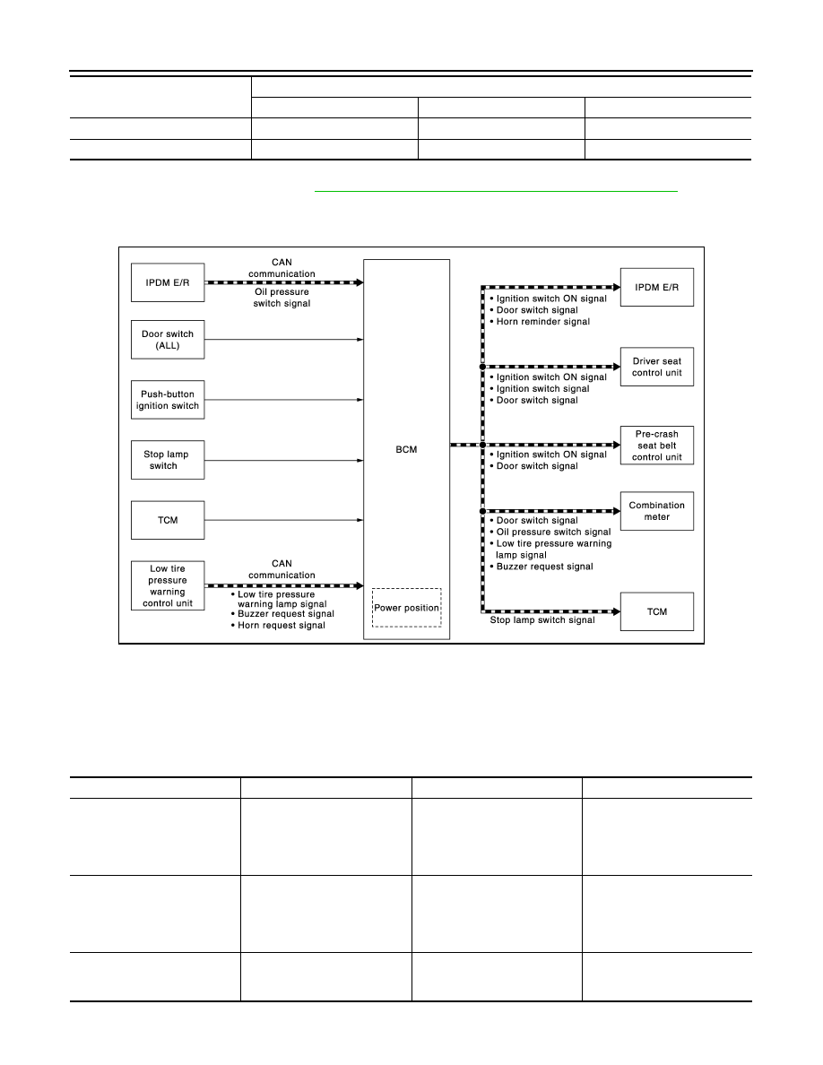
SIGNAL BUFFER SYSTEM : System Diagram

INFOID:0000000006274792

SIGNAL BUFFER SYSTEM : System Description

INFOID:0000000006274793

OUTLINE

BCM has the signal transmission function that outputs/transmits each input/received signal to each unit.

Signal transmission function list

6

OFF

ON

ON

7

OFF

ON

OFF

Wiper volume

dial position

Switch status

WIP VOLUME 1

WIP VOLUME 2

WIP VOLUME 3

JMMIA0381GB

Signal name

Input

Output

Description

• Ignition switch ON signal
• Ignition switch signal

Push-button ignition switch 
(Push switch)

• IPDM E/R (CAN)
• Driver seat control unit (CAN)
• Pre-crash seat belt control 

unit (CAN)

Inputs the push-button ignition 
switch (push switch) signal and 
transmits the ignition switch sta-
tus judged with BCM via CAN 
communication.

Door switch signal

Any door switch

• Combination meter (CAN)
• IPDM E/R (CAN)
• Driver seat control unit (CAN)
• Pre-crash seat belt control 

unit (CAN)

Inputs the door switch signal 
and transmits it via CAN com-
munication.

Oil pressure switch signal

IPDM E/R (CAN)

Combination meter (CAN)

Transmits the received oil pres-
sure switch signal via CAN 
communication.

BCS

SYSTEM

BCS-11

< SYSTEM DESCRIPTION >

C

D

E

F

G

H

I

J

K

L

B

A

O

P

N

POWER CONSUMPTION CONTROL SYSTEM

POWER CONSUMPTION CONTROL SYSTEM : System Diagram

INFOID:0000000006274794

POWER CONSUMPTION CONTROL SYSTEM : System Description

INFOID:0000000006274795

OUTLINE

• BCM incorporates a power saving control function that reduces the power consumption according to the

vehicle status. 

• BCM switches the status (control mode) by itself with the power saving control function. It performs the sleep

request to each unit (IPDM E/R, combination meter, driver seat control unit, automatic back door control
module, pre-crash seat belt control unit and CAN gateway) that operates with the ignition switch OFF.

Normal mode (wake-up)

- CAN communication is normally performed with other units
- Each control with BCM is operating properly

CAN communication sleep mode (CAN sleep)

- CAN transmission is stopped
- Control with BCM only is operating

Stop lamp switch signal

Stop lamp switch

TCM (CAN)

Inputs the stop lamp switch 1 
signal and stop lamp switch 2 
signal, and transmits it via CAN 
communication.

Low tire pressure warning lamp 
signal

Low tire pressure warning con-
trol unit

Combination meter (CAN)

Transmits the received low tire 
pressure warning signal via 
CAN communication.

Buzzer request signal

Low tire pressure warning con-
trol unit

Combination meter (CAN)

Transmits the received buzzer 
request signal via CAN commu-
nication.

Horn request signal

Low tire pressure warning con-
trol unit

IPDM E/R (CAN)

Received the horn request sig-
nal, transmits the horn reminder 
signal via CAN communication.

Signal name

Input

Output

Description

JMMIA0382GB

BCS-12

< SYSTEM DESCRIPTION >

SYSTEM

Low power consumption mode (BCM sleep)

- Low power consumption control is active
- CAN transmission is stopped

LOW POWER CONSUMPTION CONTROL WITH BCM

BCM reduces the power consumption with the following operation in the low power consumption mode.
• The reading interval of the each switches changes from 10 ms interval to 60 ms interval.

Sleep mode activation

• BCM receives the sleep-ready signal (ready) from IPDM E/R, combination meter and automatic back door

control module via CAN communication.

• BCM transmits the sleep wake up signal (sleep) to each unit when all of the CAN sleep conditions are ful-

filled.

• Each unit stops the transmission of CAN communication with the sleep wake up signal. BCM is in CAN com-

munication sleep mode.

• BCM is in the low power consumption mode and perform the low power consumption control when all of the

BCM sleep conditions are fulfilled with CAN sleep condition.

Sleep condition

Wake-up operation

• BCM transmits sleep wake up signal (wake up) to each unit when any condition listed below is established,

and then goes into normal mode from low power consumption mode.

• Each unit starts transmissions with CAN communication by receiving sleep wake up signals. Each unit trans-

mit wake up signals to BCM with CAN communication to convey the start of CAN communication.

CAN sleep condition

BCM sleep condition

• Receiving the sleep-ready signal (ready) from all units
• Ignition switch: OFF
• Vehicle security system: Not operation
• Warning chime: Not operation
• Intelligent Key system buzzer: Not operation
• Stop lamp switch: OFF
• Turn signal indicator lamp: Not operation
• Exterior  lamp:  OFF
• Door lock status: No change
• CONSULT-III communication status: Not communication
• Meter display signal: Non-transmission
• Door switch status: No change
• Rear window defogger: OFF
• Driver door lock status: No change

• Interior room lamp battery saver: Time out
• RAP system: OFF
• IVIS: Not operation
• Remote keyless entry receiver communication status: No com-

munication

• LOCK indicator lamp: Not operation
• ACC indicator lamp: Not operation
• ON indicator lamp: Not operation

BCS

SYSTEM

BCS-13

< SYSTEM DESCRIPTION >

C

D

E

F

G

H

I

J

K

L

B

A

O

P

N

Wake-up condition

Wake-up condition

• Receiving the sleep-ready signal (Not-ready) from any units
• Push-button ignition switch (push switch): OFF

 ON

• Hazard switch: ON
• HI BEAM switch: OFF 

 ON, ON 

 OFF

• PASSING switch: OFF 

 ON, ON 

 OFF

• HEADLAMP 1 switch: OFF 

 ON, ON 

 OFF

• HEADLAMP 2 switch: OFF 

 ON, ON 

 OFF

• TAIL LAMP switch: OFF 

 ON

• FR FOG switch: OFF 

 ON, ON 

 OFF

• TURN RH: OFF 

 ON, ON 

 OFF

• TURN LH: OFF 

 ON, ON 

 OFF

• Driver door switch: OFF 

 ON, ON 

 OFF

• Passenger door switch: OFF 

 ON, ON 

 OFF

• Rear RH door switch: OFF 

 ON, ON 

 OFF

• Rear LH door switch: OFF 

 ON, ON 

 OFF

• Back door switch: OFF 

 ON, ON 

 OFF

• Driver door request switch: OFF 

 ON

• Passenger door request switch: OFF 

 ON

• Back door request switch: OFF 

 ON

• Back door opener switch: OFF 

 ON

• Stop lamp switch: ON
• Door lock and unlock switch:

NEUTRAL 

 LOCK, NEUTRAL 

 UNLOCK

• Front door lock assembly (driver side) (door key cylinder switch):

NEUTRAL 

 LOCK, NEUTRAL 

 UNLOCK

• Remote keyless entry receiver communication: Receiving
• Front door lock assembly (driver side) (unlock sensor):

OFF 

 ON, ON 

 OFF


Content   ..  97  98  99  100   ..