Infiniti QX56 (Z62). Manual - part 54
AV-70
< ECU DIAGNOSIS INFORMATION >
BOSE AMP.
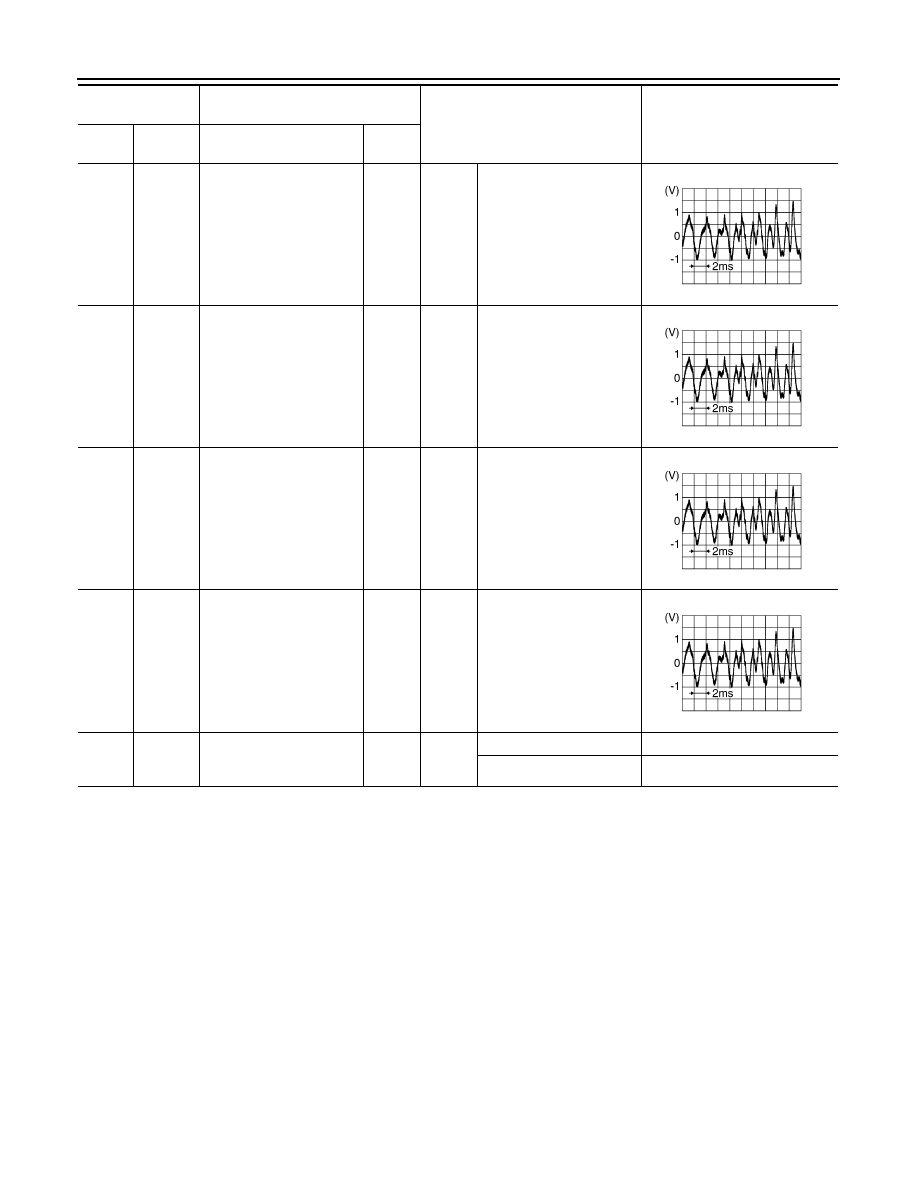
29
(GR/R)
30
(G/R)
Sound signal center speak-
er
Output
Ignition
switch
ON
Sound output
31
(L/W)
32
(L)
Sound signal front door
speaker RH
Output
Ignition
switch
ON
Sound output
33
(Y/L)
34
(Y/G)
Sound signal front RH
Input
Ignition
switch
ON
Sound output
35
(L)
36
(P)
Sound signal front LH
Input
Ignition
switch
ON
Sound output
37
(R/W)
Ground
Mode change signal
Input
Ignition
switch
ON
Driver's Audio Stage ON
0 V
Driver's Audio Stage OFF
8.5 V
Terminal
(Wire color)
Description
Condition
Reference value
(Approx.)
+
–
Signal name
Input/
Output
SKIB3609E
SKIB3609E
SKIB3609E
SKIB3609E