Infiniti QX56 (Z62). Manual - part 43


  Index      Infiniti     Infiniti QX56 (Z62) - service repair manual 2011 year


Search            


Content   ..  41  42  43  44   ..


Infiniti QX56 (Z62). Manual - part 43


AV-26

< SYSTEM DESCRIPTION >

SYSTEM

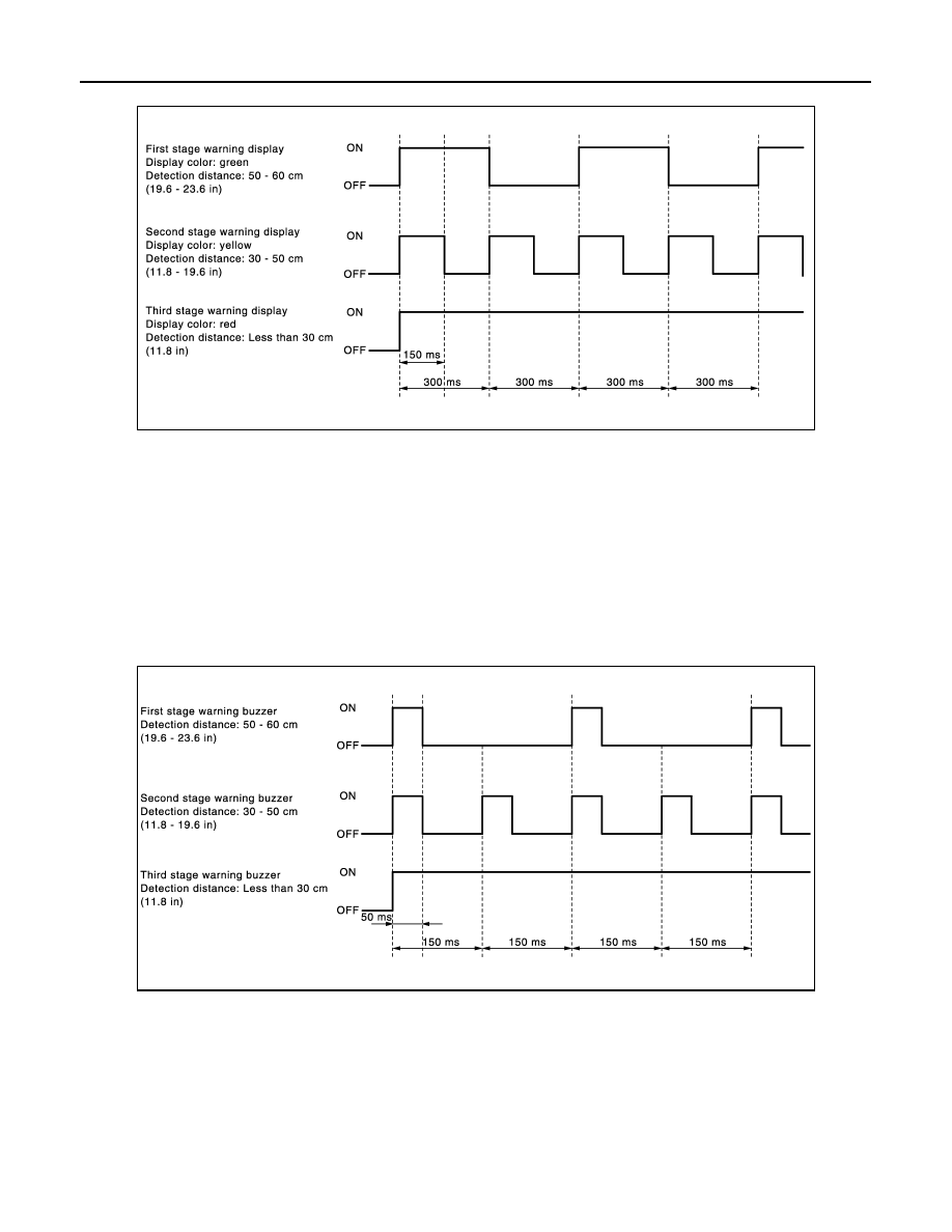
Color and blinking cycle of sonar indicator

Sonar Buzzer Operation

• Each sonar sensor transmits a sensor signal to the sonar control unit when detecting an obstacle.
• The sonar control unit converts a signal received from each sonar sensor into distance and transmits detec-

tion distance signal to the AV control unit via AV communication.

• The AV control unit transmits a buzzer signal to the BOSE amp. corresponding to each sonar sensor based

on the received signal.

• When receiving a buzzer signal, the BOSE amp. transmits the buzzer signal to the each speaker. When

each speaker receives a buzzer signal, a buzzer sounds.

• When the front corner sensor detects an obstacle, a buzzer is heard from the speakers on the front side.
• When the rear corner sensor detects an obstacle, a buzzer is heard from the speakers on the rear side.
• It changes the buzzer cycle in 3 stages according to the detection distance. 

Sonar buzzer cycle

VEHICLE INFORMATION FUNCTION

• Status of audio, climate control system, fuel economy, maintenance and navigation are displayed.
• AV control unit displays the fuel consumption status while receiving data signal through CAN communication

from ECM and combination meter.

• AV control unit is connected to BCM via CAN communication transmitting/receiving for the vehicle settings

function.

AUTO LIGHT ADJUSTMENT SYSTEM

JSNIA3149GB

JSNIA3150GB

AV

SYSTEM

AV-27

< SYSTEM DESCRIPTION >

C

D

E

F

G

H

I

J

K

L

M

B

A

O

P

When the light switch is in the 1st or 2nd position, the dimming of the display is judged according to a dimming
signal transmitted from BCM to the AV control unit. Display illuminance is independent of vehicle exterior illu-
minance detected by the auto light detecting sensor even when the light switch is in 1st or 2nd position.

MULTI AV SYSTEM : Fail-Safe

INFOID:0000000006216217

When the ambiance temperature becomes extremely low or extremely high, AV control unit displays the mes-
sage and limits the AV control unit function. 

FAIL-SAFE CONDITIONS

When the ambiance temperature is 

20

°

C (

4

°

F) or lower, or when it is 70

°

C (158

°

F) or higher

Display

The messages displayed on fail-safe conditions are as shown below:

DESCRIPTION OF CONTROLS

Ability Operation Mode 

There is an ability operation mode for Fail-safes due to low or high ambiance temperature.
If HDD data can be read, fail-safe is shown, then normal displays are displayed only for functions which can be
operated.

RELEASE CONDITIONS OF FAIL-SAFE 

Fail-safe is released on following conditions and normal mode is restored.

When The Temperature of HDD Is Low or High

If the ambient temperature becomes out of fail-safe condition range, normal mode is restored.

Fail-safe mode

Display (display of the fail-safe condition)

When HDD temperature is low

HDD system is experiencing problems due to extreme low temperature.
Normal operation will resume when temperature rises.

When HDD temperature is high

HDD system is experiencing problems due to extreme high temperature.
Normal operation will resume when temperature drops.

Function

When Fail-safe Function is activated 

Air conditioner

Operation

Only multifunction switch (preset switch) can be operated.

Display

• LED of multifunction switch (preset switch) illuminates.
• Aimed temperature, blow angle, and flow rate are displayed in simplified mode. 

Audio

Operation

Only ON/OFF and volume control operations by multifunction switch (preset switch) are possible.

Display

No display (“Fail-safe mode” is displayed)

Camera

Operation

Image tone cannot be controlled.

Display

Cannot be superimposed. (warning display, tone control display)

Hands-free phone

Operation

Cannot be operated.

Navigation

Operation

Cannot be operated.

Self diagnosis

The display in simplified mode of fail-safe condition

CONSULT-III diagnosis

Cannot be operated.

AV-28

< SYSTEM DESCRIPTION >

DIAGNOSIS SYSTEM (AV CONTROL UNIT)

DIAGNOSIS SYSTEM (AV CONTROL UNIT)

Description

INFOID:0000000006216218

• The AV control unit diagnosis function starts up with multifunction switch operation and the AV control unit

performs a diagnosis for each unit in the system during the on board diagnosis.

• Perform a CONSULT-III diagnosis if the on board diagnosis does not start, e.g., the screen does not display

anything, the multifunction switch does not function, etc.

On Board Diagnosis Function

INFOID:0000000006216219

MULTIFUNCTION SWITCH AND PRESET SWITCH SELF-DIAGNOSIS FUNCTION

The ON/OFF operation (continuity) of each switch in the multifunction switch and preset switch can be
checked.

Self-diagnosis Mode

• Press the “BACK” switch and the “UP” switch of the 8-direction

switches within 10 seconds after turning the ignition switch from
OFF to ACC and hold them for 3 seconds or more. Then the
buzzer sounds, all indicators of the preset switch illuminate, and
the self-diagnosis mode starts.

• The continuity of each switch at the ON position can be checked

by pressing the switch. The buzzer sounds if the switch is normal.
NOTE:
The hazard switch and disk eject switch cannot be checked.

Finishing Self-diagnosis Mode

Self-diagnosis mode is canceled when turning the ignition switch OFF.

ON BOARD DIAGNOSIS

Description

• The trouble diagnosis function has a self-diagnosis mode for conducting trouble diagnosis automatically and

a confirmation/adjustment mode for operating manually.

• The self-diagnosis mode performs diagnoses on the AV control unit, connections between system compo-

nents as well as connections between AV control unit and GPS antenna. Then it displays the diagnosis
results on the display.

• The confirmation/adjustment mode allows the technician to check, modify or adjust the vehicle signals and

set values, as well as to monitor the system error records and system communication status. The checking,
modifying or adjusting generally require human intervention and judgment (the system cannot make judg-
ment automatically). 

On Board Diagnosis Item

JSNIA2987ZZ

Mode

Description

Self Diagnosis

• AV control unit diagnosis.
• Diagnoses the connections across system components, between AV 

control unit and GPS antenna.

AV

DIAGNOSIS SYSTEM (AV CONTROL UNIT)

AV-29

< SYSTEM DESCRIPTION >

C

D

E

F

G

H

I

J

K

L

M

B

A

O

P

METHOD OF STARTING

1.

Start the engine.

2.

Turn the audio system OFF.

3.

While pressing the “SETTING” button, turn the volume control
dial clockwise or counterclockwise for 40 clicks or more. (When
the self-diagnosis mode is started, the trouble diagnosis initial
screen is displayed.)
• Shifting from current screen to previous screen is performed

by pressing “BACK” button.

Confirmation/

Adjustment

Display Diagnosis

The following check functions are available: color tone check by color 
bar display and white display, light and shade check by gray scale dis-
play and touch panel calibration response check.

Vehicle Signals

Diagnosis of signals can be performed for vehicle speed, parking brake, 
lights, ignition, reverse, side view switch and room lamp.

Speaker Test

The connection of a speaker can be confirmed by test tone.

Navigation

Steering Angle Ad-
justment

When there is a difference between the actual turning angle and the ve-
hicle mark turning angle, it can be adjusted.

Speed Calibration

When there is a difference between the current location mark and the ac-
tual location, it can be adjusted.

Error History

The system malfunction and the frequency when occurring in the past 
are displayed. When the malfunctioning item is selected, the time and 
place that the selected malfunction last occurred are displayed.

Synchronizer FES Clock

Vehicle CAN Diagnosis

The transmitting/receiving of CAN communication can be monitored.

AV COMM Diagnosis

The communication condition of each unit of Multi AV system can be 
monitored.

Handsfree Phone

The received volume adjustment of hands-free phone, microphone 
speaker check, and erase memory can be performed.

Camera

It can perform the confirmation of a signal connection to around view 
monitor control unit, the calibration of each camera, Correct Draw Line 
of Camera Image, and Fine Tuning of Birds-Eye View.

XM

XM NaviTrffic

Change Channel

• Any necessary channels required to receive traffic information from 

the satellite radio system can be set.
Change Application ID

• Any application ID'-s required to receive traffic information from the 

satellite radio system can be set.

XM NavWeather

XM CGS

Diag

Delete Unit Connection Log

Erase the connection history of unit and error history.

Initialize Settings

Initializes the AV control unit memory.

Version Information

Version information of the AV control unit is displayed.

Mode

Description

JSNIA2993ZZ


Content   ..  41  42  43  44   ..