Infiniti QX4 (R50). Manual - part 595
SMT016D
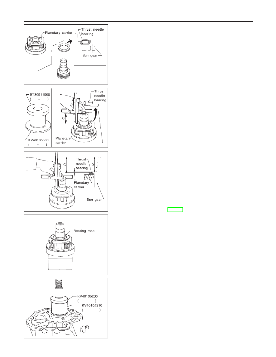
6.
Install thrust needle bearing to sun gear.
7.
Install sun gear to planetary carrier.
SMT017D
8.
Set a support (KV40105500) to bushing replacer puller
(ST30911000) as shown in the figure, and place planetary
carrier on it.
9.
Install thrust needle bearing to planetary carrier with its roller
facing front case.
10. Measure “C” from the end of sun gear to the roller surface of
thrust needle bearing.
SMT018D
11. Measure “D” from the end of sun gear to the main gear bear-
ing contact surface.
12. Calculate end play “E” using “C” and “D” obtained in steps 10
and 11. Select bearing race so that the end play becomes the
standard value.
Calculation formula:
End play “E” = “C” − “D”
Standard end play:
0.1 - 0.25 mm (0.0039 - 0.0098 in)
Bearing race:
Refer to SDS, TF-159.
SMT019D
13. Set planetary carrier to press in the status described in step 8.
Then install the selected bearing race to planetary carrier.
SMT020D
14. Install front case to planetary carrier. Set a support ring
(KV40105310) and an adapter B (KV40105230) to main gear
bearing inner race, then press it.
ASSEMBLY
Front Case (Cont’d)
TF-142