Infiniti QX4 (R50). Manual - part 578
4
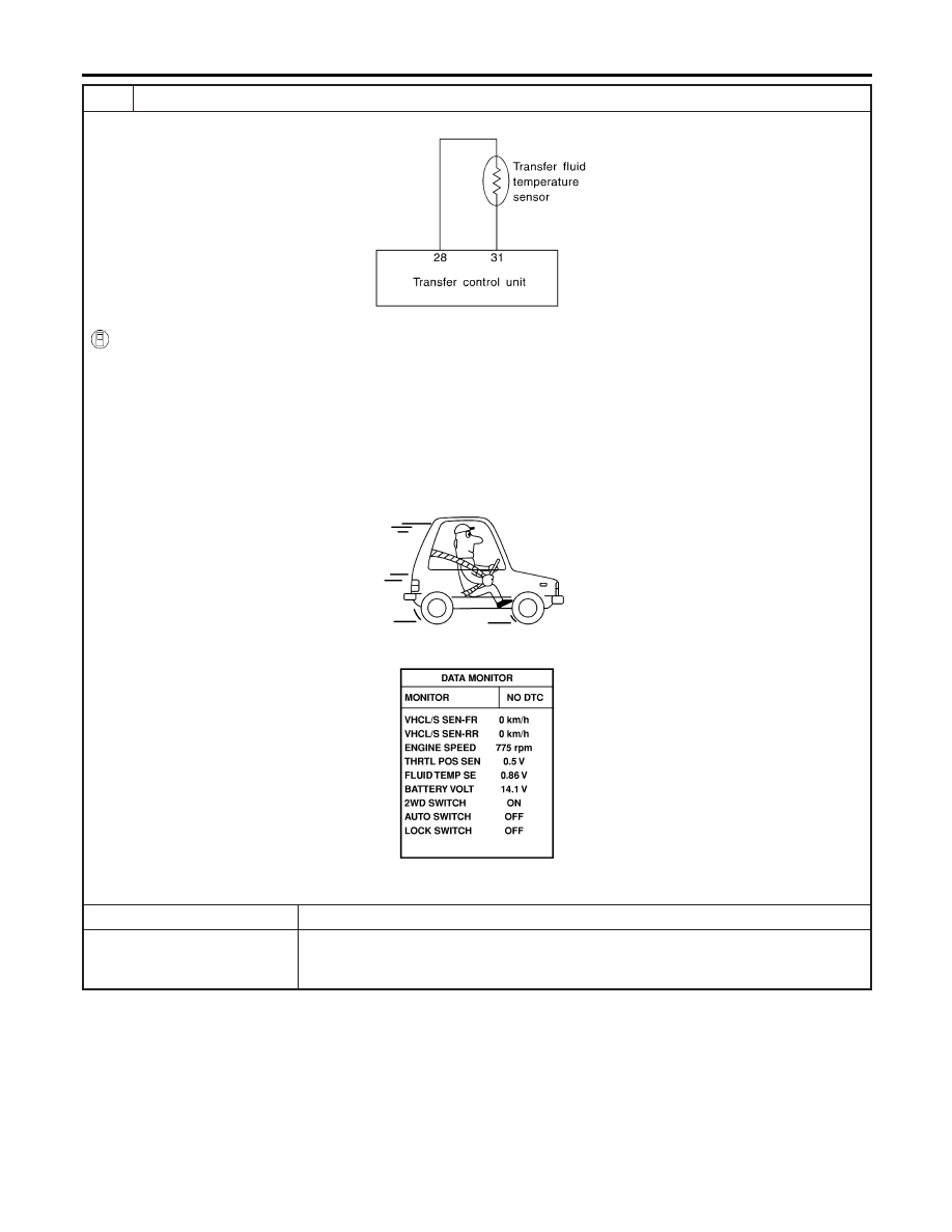
CHECK INPUT SIGNAL
SMT784D
With CONSULT-II
1. Start engine.
2. Select “ECU INPUT SIGNALS” in Data Monitor.
3. Read out the value of “FLUID TEMP SE”.
Voltage:
20°C (68°F): Approx. 1.5V
80°C (176°F): Approx. 0.5V
SMT974D
OK or NG
OK
©
GO TO 6.
NG
©
Check the following.
I
Continuity between transfer control unit and transfer terminal cord assembly sub-har-
ness connector
TRANSFER FLUID TEMPERATURE SENSOR
Diagnostic Procedure (Cont’d)
TF-74