Infiniti QX4 (R50). Manual - part 567
Flickering pattern or flick-
ering condition
Malfunction
Check items
No flickering
PNP switch or 4WD shift switch circuit is shorted or open.
PNP switch (Refer to AT-99, “DTC
P0705 Park/Neutral Position
Switch”.) or 4WD shift switch circuit,
TF-66.
*: If revolution sensor malfunction is simultaneously detected, check revolution sensor first.
SAT601J
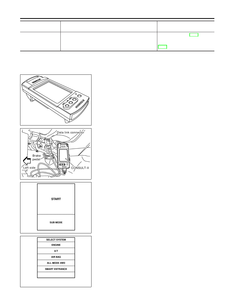
Trouble Diagnosis with CONSULT-II
NBTF0012
SELF-DIAGNOSIS
NBTF0012S01
CONSULT-II Setting Procedure
NBTF0012S0101
1.
Turn ignition switch to “OFF” position.
SMT962D
2.
Connect CONSULT-II to data link connector which is located
in instrument lower panel on driver side.
SAT586J
3.
Start engine.
4.
On CONSULT-II screen, touch “START”.
SMT964D
5.
Touch “ALL MODE 4WD” on SELECT SYSTEM screen.
ON BOARD DIAGNOSTIC SYSTEM DESCRIPTION
Trouble Diagnosis without CONSULT-II (Cont’d)
TF-30