Infiniti QX4 (R50). Manual - part 555


  Index      Infiniti     Infiniti QX4 (R50) - service repair manual 2001 year


Search            copyright infringement  


Content   ..  553  554  555  556   ..


Infiniti QX4 (R50). Manual - part 555


SBR686C

Precautions

PRECAUTIONS

NBSU0001

I

When installing rubber parts, final tightening must be car-
ried out under unladen condition* with tires on ground.
*Fuel, radiator coolant and engine oil full. Spare tire, jack,
hand tools and mats in designated positions.

I

Use flare nut wrench when removing and installing brake
tubes.

I

After installing removed suspension parts, check wheel
alignment and adjust if necessary.

I

Always torque brake lines when installing.

Preparation

SPECIAL SERVICE TOOLS

NBSU0002

The actual shapes of Kent-Moore tools may differ from those of special service tools illustrated here.

Tool number
(Kent-Moore No.)
Tool name

Description

ST29020001
(J24319-01)
Ball joint remover

NT694

Removing tie-rod outer end and lower ball joint
a: 34 mm (1.34 in)
b: 6.5 mm (0.256 in)
c: 61.5 mm (2.421 in)

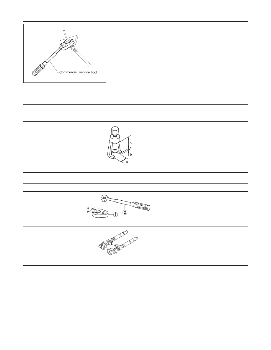
COMMERCIAL SERVICE TOOLS

NBSU0003

Tool name

Description

1 Flare nut crowfoot
2 Torque wrench

NT360

Removing and installing each brake piping
a: 10 mm (0.39 in)

Spring compressor

NT717

Removing and installing coil spring

FRONT SUSPENSION

Precautions

SU-2

Noise, Vibration and Harshness (NVH)
Troubleshooting

=NBSU0035

NVH TROUBLESHOOTING CHART

NBSU0035S01

Use the chart below to help you find the cause of the symptom. If necessary, repair or replace these parts.

Reference page

SU-4,

16

SU-8,

18

SU-8,

18

SU-6

SU-10,

20

SU-6

PD-3

PD-3

AX-3

AX-3

Refer

to

SUSPENSION

in

this

chart.

Refer

to

TIRES

in

this

chart.

Refer

to

ROAD

WHEEL

in

this

chart.

BR-6

ST

-6

Possible cause and
SUSPECTED
PARTS

Improper

installation,

looseness

Shock

absorber

deformation,

damage

or

deflection

Bushing

or

mounting

deterioration

Parts

interference

Spring

fatigue

Suspension

looseness

Incorrect

wheel

alignment

Stabilizer

bar

fatigue

Out-of-round

Imbalance

Incorrect

air

pressure

Uneven

tire

wear

Deformation

or

damage

Non-uniformity

Incorrect

tire

size

PROPELLER

SHAFT

DIFFERENTIAL

DRIVE

SHAFT

AXLE

SUSPENSION

TIRES

ROAD

WHEEL

BRAKES

STEERING

Symptom

SUSPENSION

Noise

×

×

×

×

×

×

×

×

×

×

×

×

×

×

Shake

×

×

×

×

×

×

×

×

×

×

×

×

Vibration

×

×

×

×

×

×

×

×

×

×

Shimmy

×

×

×

×

×

×

×

×

×

×

Judder

×

×

×

×

×

×

×

×

Poor quality
ride or han-
dling

×

×

×

×

×

×

×

×

×

×

TIRES

Noise

×

×

×

×

×

×

×

×

×

×

×

×

×

×

×

Shake

×

×

×

×

×

×

×

×

×

×

×

×

×

×

Vibration

×

×

×

×

×

×

×

Shimmy

×

×

×

×

×

×

×

×

×

×

×

×

×

Judder

×

×

×

×

×

×

×

×

×

×

×

×

Poor quality
ride or han-
dling

×

×

×

×

×

×

×

×

×

×

ROAD

WHEEL

Noise

×

×

×

×

×

×

×

×

×

×

×

×

Shake

×

×

×

×

×

×

×

×

×

×

×

Shimmy,
Judder

×

×

×

×

×

×

×

×

×

Poor quality
ride or han-
dling

×

×

×

×

×

×

×

×

: Applicable

GI

MA

EM

LC

EC

FE

AT

TF

PD

AX

BR

ST

RS

BT

HA

SC

EL

IDX

FRONT SUSPENSION

Noise, Vibration and Harshness (NVH) Troubleshooting

SU-3

Components

NBSU0004

SFA744B

1.

Strut mounting insulator

2.

Spring upper seat

3.

Bound bumper

4.

Coil spring

5.

Strut assembly

6.

Stabilizer connecting rod

7.

Bracket

8.

Stabilizer bar

9.

Transverse link

10. Drive shaft

FRONT SUSPENSION

Components

SU-4

SMA525A

On-vehicle Service

FRONT SUSPENSION PARTS

NBSU0005

Check front axle and front suspension parts for excessive play,
cracks, wear and other damage.
1.

Shake each front wheel to check for excessive play.

2.

Retighten all axle and suspensions nuts and bolts to the speci-
fied torque.

Tightening torque:

Refer to “Components”, SU-8.

SFA392B

3.

Check strut (shock absorber) for oil leakage and other dam-
age.

4.

Check suspension ball joint for grease leakage and ball joint
dust cover for cracks and other damage.
If ball joint dust cover is cracked or damaged, replace ball joint
assembly.

5.

Check suspension ball joint end play.

a.

Jack up front of vehicle and set the stands.

b.

Clamp dial indicator onto transverse link and place indicator tip
on lower edge of brake caliper.

c.

Make sure front wheels are straight and brake pedal is
depressed.

SFA745B

d.

Place a pry bar between transverse link and knuckle.

e.

While raising and releasing pry bar, observe maximum dial
indicator value.

Vertical end play:

0 mm (0 in)

If ball joint vertical end play exists, remove lower ball joint
assembly and recheck the ball joint. Refer to “Tranverse Link
and Lower Ball Joint”, SU-11.

SFA746B

6.

Check spring height from top of wheelarch to ground using the
following procedure.

a.

Park vehicle on a level surface with vehicle unladen*.
*: Fuel, radiator coolant and engine oil full. Spare tire, jack,
hand tools and mats in designated positions.

b.

Check tires for proper inflation and wear (tread wear indicator
must not be showing).

c.

Bounce vehicle up and down several times and measure
dimensions Hf and Hr. Refer to SDS, SU-14.
Spring height is not adjustable. If out of specification, check for
worn springs and suspension parts.

GI

MA

EM

LC

EC

FE

AT

TF

PD

AX

BR

ST

RS

BT

HA

SC

EL

IDX

FRONT SUSPENSION

On-vehicle Service

SU-5


Content   ..  553  554  555  556   ..