Infiniti QX4 (R50). Manual - part 553


  Index      Infiniti     Infiniti QX4 (R50) - service repair manual 2001 year


Search            copyright infringement  


Content   ..  551  552  553  554   ..


Infiniti QX4 (R50). Manual - part 553


Disassembly

NBST0034

CAUTION:

I

Parts which can be disassembled are strictly limited.
Never disassemble parts other than those specified.

I

Disassemble in as clean a place as possible.

I

Clean your hands before disassembly.

I

Do not use rags; use nylon cloths or paper towels.

I

Follow the procedures and cautions in the Service
Manual.

I

When disassembling and reassembling, do not let foreign
matter enter or contact the parts.

1.

Fix power steering pump to vise.

CAUTION:

When fixing the pump to vise, use an aluminum plate or such
to avoid damaging the fitting plane of the steering pump.
2.

Remove the front bracket mounting bolt, and remove the front
bracket from the casing.

3.

Remove the rear cover mounting bolt, and remove the rear
cover from the casing.

4.

Remove the O-ring from the casing.

SST926C

5.

Remove side plate (rear side) from cam ring, then remove side
plate inner/outer seals from side plate (rear side).
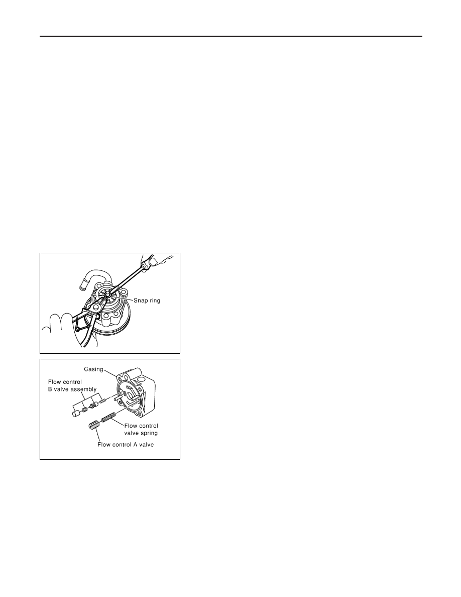
6.

Remove rotor snap ring using snap ring pliers, and remove
pulley from casing.

CAUTION:

Do not damage pulley shaft when removing rotor snap ring.

SST928C

7.

Remove the followings from casing.

I

Cam ring

I

Rotor

I

Vane

I

Side plate (front side)

I

Flow control A valve

I

Flow control valve spring

I

Flow control B valve assembly

CAUTION:

Be careful not to drop flow control valve.
8.

Remove inlet connector mounting bolt, and remove inlet con-
nector from casing.

9.

Remove inlet connector seal from inlet connector.

10. Remove drive shaft seal from casing with a screwdriver.

CAUTION:

Do not damage casing surface with the screwdriver.

POWER STEERING OIL PUMP

Disassembly

ST-28

Inspection

NBST0035

I

If pulley is cracked or deformed, replace it.

I

If an oil leak is found around pulley shaft oil seal, replace the
seal.

I

Check the casing and the inside of the rear body for damage.
If damages are found in the rear body, replace the entire rear
body. If the casing is damaged, replace the entire power steer-
ing pump as an assembly.

I

Check the cam ring for damage. If damage is found, replace
the cam ring, rotor and vane as a set.

I

Check the side plates (front and rear) for damage. If damage
is found, replace the side plates as a set (front and rear).

SST934C

Assembly

NBST0036

1.

Apply grease to the lip of the drive shaft seal, and attach the
casing.

CAUTION:

The drive shaft seal cannot be reused. Always replace after
every disassembly.

SST928C

2.

When removing the dowel pin, if it is difficult to insert with your
hands, insert into the casing by tapping lightly with a hammer
or similar tool.

3.

Attach the flow control A valve, flow control valve spring, and
the flow control B valve assembly to the locations indicated in
the drawing left.

SST929C

4.

Match the dowel pin A on the flow control A valve side with the
notch B of the side plate (front), and attach the side plate (front)
to the casing.

GI

MA

EM

LC

EC

FE

AT

TF

PD

AX

SU

BR

RS

BT

HA

SC

EL

IDX

POWER STEERING OIL PUMP

Inspection

ST-29

SST930C

5.

Face the cam ring side with fewer pores towards the casing,
and attach the cam ring on top of the side plate (front).

6.

Attach the pulley to the casing.

CAUTION:

Attach with care so as not to damage the drive shaft seal.

SST289A

7.

Face the side of the rotor with the punch mark towards the
casing, and attach the rotor to the pulley shaft.

SST843A

8.

Attach the vane to the rotor so that the vane’s arc touches the
cam ring.

SST931C

9.

Use a hammer or suitable tool to insert the rotor snap ring into
the pulley shaft channel.

CAUTION:

I

The rotor snap ring cannot be reused. Always replace after
every disassembly.

I

Insert with care so as not to damage the rotor or the pul-
ley shaft.

I

If the rotor is damaged, replace the power steering as an
assembly.

SST932C

10. Match the dowel pin A on the flow control A valve side with the

notch B of the side plate (rear), and attach the side plate (rear)
to the cam ring.

11. Apply Genuine Nissan PSF II or equivalent to O-ring and

attach to the casing.

CAUTION:

The O-ring cannot be reused. Always replace after every dis-
assembly.

POWER STEERING OIL PUMP

Assembly (Cont’d)

ST-30

SST933C

12. Attach a side plate inner seal and side plate outer seal with

Genuine Nissan PSF II or equivalent applied, to the side plate
(rear).

CAUTION:

The side plate inner seal and outer seal cannot be reused.
Always replace after every disassembly.
13. Set the power steering pump on the vice.

CAUTION:

When securing to the vice, use an aluminum plate or other
material to protect the installation surface of the power steer-
ing pump from damage.
14. Attach the rear body to the casing, and secure the bolts (4

bolts) in a diagonal order to the specified torque.

15. Attach the front bracket to the casing, and secure the bolts (2

bolts) to the specified torque.

16. Attach the inlet collector seal to the grooves of the inlet

collector, and attach the inlet collector to the casing with
attachment bolts.

CAUTION:

The inlet collector seal cannot be reused. Always replace after
every disassembly.

GI

MA

EM

LC

EC

FE

AT

TF

PD

AX

SU

BR

RS

BT

HA

SC

EL

IDX

POWER STEERING OIL PUMP

Assembly (Cont’d)

ST-31


Content   ..  551  552  553  554   ..