Infiniti QX4 (R50). Manual - part 495


  Index      Infiniti     Infiniti QX4 (R50) - service repair manual 2001 year


Search            copyright infringement  


Content   ..  493  494  495  496   ..


Infiniti QX4 (R50). Manual - part 495


I

Inspect the oil cooler after removing it.

SLC333B

3.

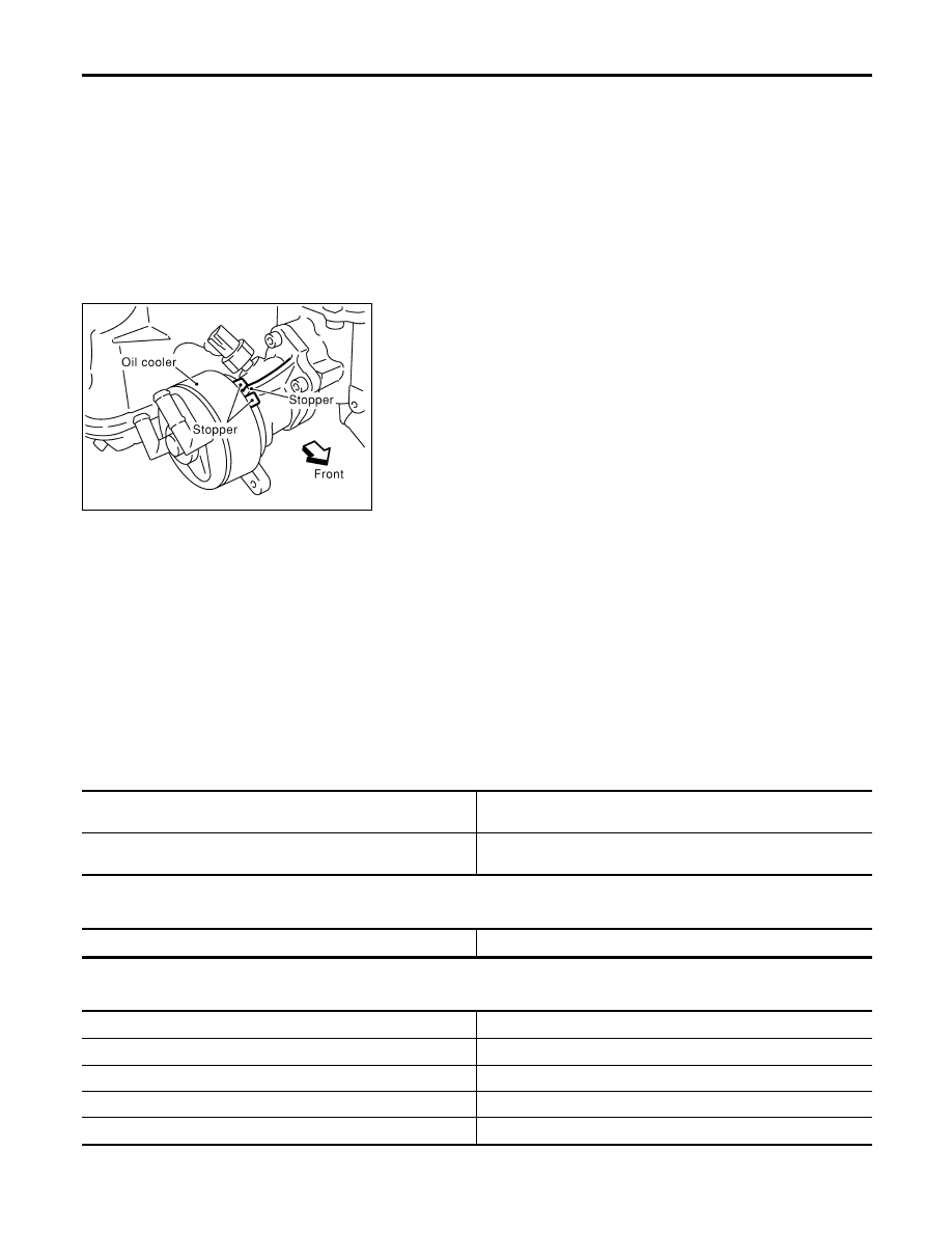
Installation is in reverse order of removal.

I

When installing the oil cooler, align the oil cooler stopper
with the stopper of the oil cooler bracket.

INSPECTION

NBLC0037

Oil Cooler

NBLC0037S01

1.

Check oil cooler for cracks.

2.

Check oil cooler for clogging by blowing through coolant inlet.
If necessary, replace oil cooler assembly.

Oil Pressure Relief Valve

NBLC0037S02

Inspect oil pressure relief valve for movement, cracks and breaks
by pushing the ball. If replacement is necessary, remove valve by
prying it out with a suitable tool. Install a new valve in place by
tapping it.

Service Data and Specifications (SDS)

OIL PRESSURE

NBLC0010

Engine speed

rpm

Approximate discharge pressure

kPa (kg/cm

2

, psi)

Idle speed

2,000

More than 98 (1.0, 14)

294 (3.0, 43)

REGULATOR VALVE

NBLC0011

Unit: mm (in)

Regulator valve to oil pump cover clearance

0.040 - 0.097 (0.0016 - 0.0038)

OIL PUMP

NBLC0012

Unit: mm (in)

Body to outer rotor radial clearance

0.114 - 0.200 (0.0045 - 0.0079)

Inner rotor to outer rotor tip clearance

Below 0.18 (0.0071)

Body to inner rotor axial clearance

0.030 - 0.070 (0.0012 - 0.0028)

Body to outer rotor axial clearance

0.050 - 0.110 (0.0020 - 0.0043)

Inner rotor to brazed portion of housing clearance

0.045 - 0.091 (0.0018 - 0.0036)

ENGINE LUBRICATION SYSTEM

Oil Cooler (Cont’d)

LC-8

SEM164F

AEM080

Precautions

LIQUID GASKET APPLICATION PROCEDURE

NBLC0013

1.

Use a scraper to remove all traces of old liquid gasket from
mating surfaces and grooves. Also, completely clean any oil
from these areas.

2.

Apply a continuous bead of liquid gasket to mating surfaces.
(Use Genuine RTV silicone sealant Part No. 999MP-A7007
or equivalent.)

I

For oil pan, be sure liquid gasket diameter is 4.0 to 5.0 mm
(0.157 to 0.197 in).

I

For areas except oil pan, be sure liquid gasket diameter is 2.0
to 3.0 mm (0.079 to 0.118 in).

3.

Apply liquid gasket around the inner side of bolt holes (unless
otherwise specified).

4.

Assembly should be done within 5 minutes after coating.

5.

Wait at least 30 minutes before refilling engine oil and engine
coolant.

Preparation

SPECIAL SERVICE TOOLS

NBLC0014

The actual shapes of Kent-Moore tools may differ from those of special service tools illustrated here.

Tool number
(Kent-Moore No.)
Tool name

Description

WS39930000
(

)

Tube pressure

NT052

Pressing the tube of liquid gasket

EG17650301
(J33984-A)
Radiator cap tester
adapter

NT564

Adapting radiator cap tester to radiator filler neck
a: 28 (1.10) dia.
b: 31.4 (1.236) dia.
c: 41.3 (1.626) dia.
Unit: mm (in)

KV99103510
(

)

Radiator plate pliers A

NT224

Installing radiator upper and lower tanks

KV99103520
(

)

Radiator plate pliers B

NT225

Removing radiator upper and lower tanks

GI

MA

EM

EC

FE

AT

TF

PD

AX

SU

BR

ST

RS

BT

HA

SC

EL

IDX

ENGINE COOLING SYSTEM

Precautions

LC-9

Cooling Circuit

NBLC0015

SLC321B

SLC325B

ENGINE COOLING SYSTEM

Cooling Circuit

LC-10

System Check

NBLC0016

WARNING:

Never remove the radiator cap when the engine is hot; serious
burns could be caused by high pressure fluid escaping from
the radiator.
Wrap a thick cloth around the cap and carefully remove it by
turning it a quarter turn to allow built-up pressure to escape
and then turn the cap all the way off.

CHECKING COOLING SYSTEM HOSES

NBLC0016S01

Check hoses for improper attachment, leaks, cracks, damage,
loose connections, chafing and deterioration.

CHECKING RADIATOR

NBLC0016S02

Check radiator for mud or clogging. If necessary, clean radiator as
follows.

I

Be careful not to bend or damage the radiator fins.

I

When radiator is cleaned without removal, remove all sur-
rounding parts such as cooling fan, radiator shroud and horns.
Then tape the harness and connectors to prevent water from
entering.

1.

Apply water by hose to the back side of the radiator core ver-
tically downward.

2.

Apply water again to all radiator core surfaces once per
minute.

3.

Stop washing if any stains no longer flow out from the radia-
tor.

4.

Blow air into the back side of radiator core vertically downward.

I

Use compressed air lower than 490 kPa (5 kg/cm

2

, 71 psi) and

keep distance more than 30 cm (11.8 in).

5.

Blow air again into all the radiator core surfaces once per
minute until no water sprays out.

SLC755A

CHECKING RADIATOR CAP

NBLC0016S03

To check radiator cap, apply pressure to cap with a tester.

Radiator cap relief pressure:

Standard

78 - 98 kPa
(0.8 - 1.0 kg/cm

2

, 11 - 14 psi)

Limit

59 - 98 kPa
(0.6 - 1.0 kg/cm

2

, 9 - 14 psi)

SMA967B

Pull the negative pressure valve to open it.
Check that it closes completely when released.

GI

MA

EM

EC

FE

AT

TF

PD

AX

SU

BR

ST

RS

BT

HA

SC

EL

IDX

ENGINE COOLING SYSTEM

System Check

LC-11


Content   ..  493  494  495  496   ..