Infiniti QX4 (R50). Manual - part 475


  Index      Infiniti     Infiniti QX4 (R50) - service repair manual 2001 year


Search            copyright infringement  


Content   ..  473  474  475  476   ..


Infiniti QX4 (R50). Manual - part 475


Blower Speed Compensation

NBHA0062S05

Sunload

NBHA0062S0501

When the in-vehicle temperature and the set temperature are very close, the blower will be operating at low
speed. The low speed will vary depending on the sunload. During conditions of high sunload, the blower low
speed is “normal” low speed (approx. 6V). During low or no sunload conditions, the low speed will drop to “low”
low speed (approx. 5V).
Ambient

NBHA0062S0502

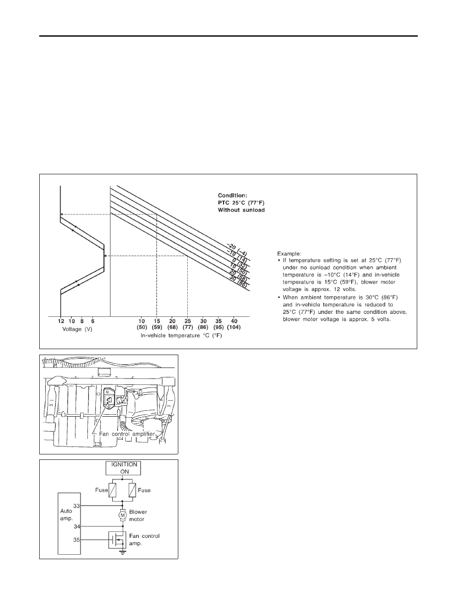
When the ambient temperature is in the “moderate” range [10 - 15°C (50 - 59°F)], the computed blower volt-
age will be compensated (reduced) by up to 3.5V (depending on the blower speed). In the “extreme” ambi-
ent ranges [below 0°C (32°F) and above 20°C (68°F)] the computed objective blower voltage is not compen-
sated at all. In the ambient temperature ranges between “moderate” and “extreme” [0 - 10°C (32 - 50°F) and
15 - 20°C (59 - 68°F)], the amount of compensation (for a given blower speed) varies depending on the ambi-
ent temperature.

Fan Speed Control Specification

NBHA0062S06

RHA138G

RHA648F

COMPONENT DESCRIPTION

NBHA0063

Fan Control Amplifier

NBHA0063S01

The fan control amplifier is located on the cooling unit. The fan
control amp. receives a gate voltage from the auto amp. to step-
lessly maintain the blower fan motor voltage in the 5 to 12 volt
range (approx.).

RHA467G

DIAGNOSTIC PROCEDURE

NBHA0064

SYMPTOM: Blower motor operation is malfunctioning under
Starting Fan Speed Control.

TROUBLE DIAGNOSES

Blower Motor (Cont’d)

HA-98

1

CHECK POWER SUPPLY FOR FAN CONTROL AMP.

Disconnect fan control amp. harness connector.
Do approx. 12 volts exist between fan control amp. harness terminal No. 3 and body ground?

RHA480G

Yes or No

Yes

©

GO TO 2.

No

©

GO TO 8.

2

CHECK BODY GROUND CIRCUIT FOR FAN CONTROL AMP.

Does continuity exist between fan control amp. harness terminal No. 1 and body ground?

RHA089G

Yes or No

Yes

©

Reconnect fan control amp. harness connector. And GO TO 3.

No

©

Repair harness or connector.

GI

MA

EM

LC

EC

FE

AT

TF

PD

AX

SU

BR

ST

RS

BT

SC

EL

IDX

TROUBLE DIAGNOSES

Blower Motor (Cont’d)

HA-99

3

CHECK VOLTAGE FOR FAN CONTROL AMP.

Set up Self-diagnosis STEP 4.
Measure voltage across fan control amp. harness terminal No. 2 and body ground.

RHA481GB

MTBL0465

OK or NG

OK

©

GO TO 5.

NG

©

I

The result is less than 2.5V. Replace fan control amp.

I

The result is more than 3.0V. GO TO 4.

4

CHECK FAN CONTROL AMP.

Refer to HA-103.

OK or NG

OK

©

GO TO 5.

NG

©

1. Replace fan control amp.
2. Go to “STEP-BY-STEP PROCEDURE”, HA-45 and perform self-diagnosis STEP 4.

Confirm that blower motor operation is normal.

5

CHECK FAN CONTROL AMP. CIRCUIT BETWEEN FAN CONTROL AMP. AND AUTO AMP. (LCU)

1. Disconnect auto amp. (LCU) and fan control amp. harness connector.
2. Check circuit continuity between auto amp. (LCU) harness terminal No. 35 and fan control amp. harness terminal No.

2.

RHA824H

Continuity should exist.

If OK, check harness for short.

OK or NG

OK

©

GO TO 6.

NG

©

Repair harness or connector.

TROUBLE DIAGNOSES

Blower Motor (Cont’d)

HA-100

6

CHECK FAN FEED BACK CIRCUIT

Reconnect auto amp. (LCU) harness connector.
Do approx. 12 volts exist between auto amp. (LCU) harness terminal No. 33 and body ground?

RHA825H

Yes or No

Yes

©

GO TO 7.

No

©

Check power supply circuit and 15A fuses (Nos. 1 and 2, located in the fuse block).
Refer to EL-14, “Wiring Diagram — POWER —”.

I

If OK, check for open circuit in wiring harness.
Repair or replace as necessary.

I

If NG, replace fuse and check wiring harness for short circuit.
Repair or replace as necessary.

7

CHECK POWER SUPPLY FOR AUTO AMP.

Do approx. 12 volts exist between auto amp. harness terminal No. 34 and body ground?

RHA826H

Yes or No

Yes

©

1. Replace auto amp.
2. Go to self-diagnosis step-by-step procedure (HA-45) and perform self-diagnosis STEP

4.
Confirm that blower motor operation is normal.

No

©

GO TO 10.

GI

MA

EM

LC

EC

FE

AT

TF

PD

AX

SU

BR

ST

RS

BT

SC

EL

IDX

TROUBLE DIAGNOSES

Blower Motor (Cont’d)

HA-101


Content   ..  473  474  475  476   ..