Infiniti QX4 (R50). Manual - part 427
8.
Cut cylinder bores.
I
When any cylinder needs boring, all other cylinders must
also be bored.
I
Do not cut too much out of cylinder bore at a time. Cut
only 0.05 mm (0.0020 in) or so in diameter at a time.
9.
Hone cylinders to obtain specified piston-to-bore clearance.
10. Measure finished cylinder bore for out-of-round and taper.
I
Measurement should be done after cylinder bore cools
down.
SEM316A
CRANKSHAFT
NBEM0027S07
1.
Check crankshaft main and pin journals for score, wear or
cracks.
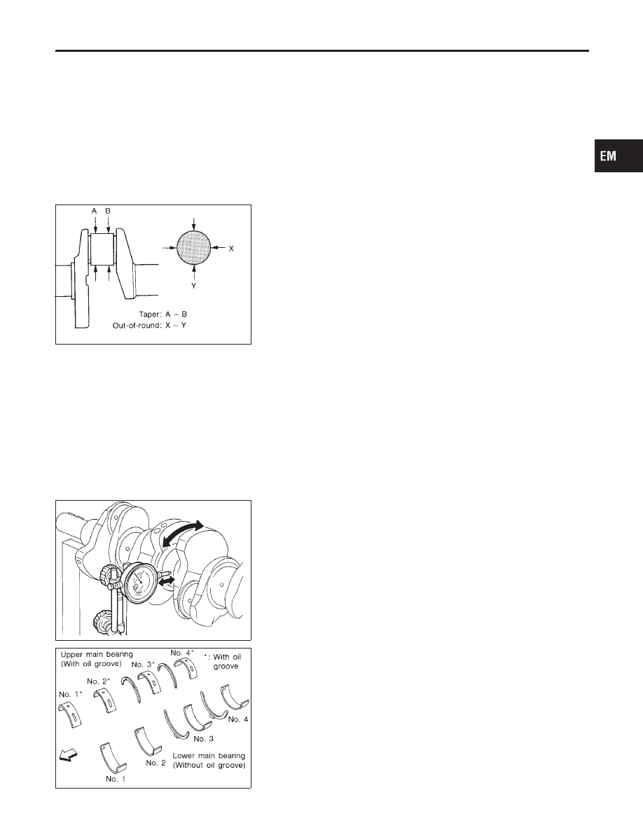
2.
With a micrometer, measure journals for taper and out-of-
round.
Out-of-round (X − Y):
Standard
0.002 mm (0.0001 in)
Taper (A − B):
Standard
0.002 mm (0.0001 in)
SEM346D
3.
Measure crankshaft runout.
Runout (Total indicator reading):
Limit 0.10 mm (0.0039 in)
SEM175F
BEARING CLEARANCE
NBEM0027S08
I
Use either of the following two methods, however, method “A”
gives more reliable results and is preferable.
Method A (Using bore gauge & micrometer)
Main bearing
NBEM0027S0801
1.
Set main bearings in their proper positions on cylinder block
and main bearing cap.
GI
MA
LC
EC
FE
AT
TF
PD
AX
SU
BR
ST
RS
BT
HA
SC
EL
IDX
CYLINDER BLOCK
Inspection (Cont’d)
EM-67