Infiniti QX4 (R50). Manual - part 413
SEM484GA
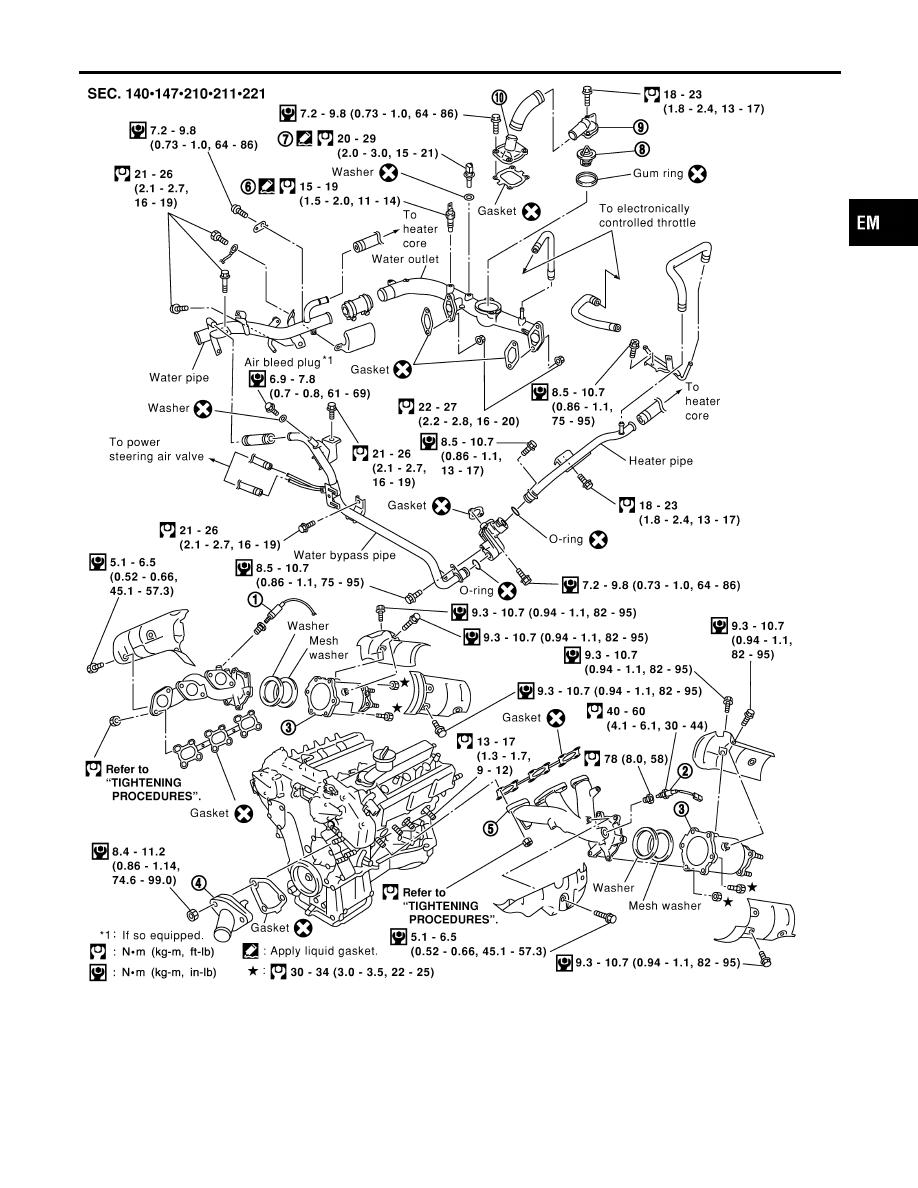
1.
Heated oxygen sensor 1 (front)
(bank 1)
2.
Heated oxygen sensor 1 (front)
(bank 2)
3.
TWC (manifold)
4.
Thermostat with water inlet
5.
Exhaust manifold
6.
Thermal transmitter
7.
Engine coolant temperature
8.
Water control valve
9.
Water outlet housing
10. Cylinder block water outlet
GI
MA
LC
EC
FE
AT
TF
PD
AX
SU
BR
ST
RS
BT
HA
SC
EL
IDX
OUTER COMPONENT PARTS
Removal and Installation (Cont’d)
EM-11