Infiniti QX4 (R50). Manual - part 393


  Index      Infiniti     Infiniti QX4 (R50) - service repair manual 2001 year


Search            copyright infringement  


Content   ..  391  392  393  394   ..


Infiniti QX4 (R50). Manual - part 393


SEL690V

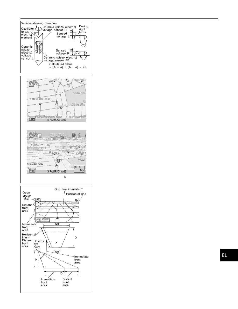
Gyro (Angular Speed Sensor)

NBEL0228S0204

I

The oscillator gyro sensor is used to detect changes in vehicle
steering angle.

I

The oscillator gyro periodically senses oscillatory variation at
the oscillation terminals. This variation is caused by changes
in the vehicle angular velocity. Voltage variations are sensed
by ceramic voltage sensors at the left and right sides of the
terminals. Vehicle angular velocity corresponds directly with
these changes in voltage.

I

The gyro is built into the display & navigation (NAVI) control
unit.

MAP DISPLAY

BIRDVIEW

R

SEL636X

BIRDVIEW

T

NBEL0228S0205

The BIRDVIEW

T

provides a detailed and easily seen display of

road conditions covering the vehicle’s immediate to distant area.

SEL691V

Description

NBEL0228S0206

I

Display area: Trapezoidal representation showing approximate
distances (Wn, D, and Wd).

I

Ten horizontal grid lines indicate display width while six verti-
cal grid lines indicate display depth and direction.

I

Drawing line area shows open space, depth, and immediate
front area. Each area is to a scale of approximately 5:6:25.

I

When the “ZM−” button is pushed, the view point height is
increased. Pushing the “ZM+” button decreases the height.
Pushing the “ZM−” button or the “ZM+” button during operation
indicates the scale change and the view point height at the
left-hand side of the screen.

GI

MA

EM

LC

EC

FE

AT

TF

PD

AX

SU

BR

ST

RS

BT

HA

SC

IDX

NAVIGATION SYSTEM

System Description (Cont’d)

EL-389

FUNCTION OF TOUCH SWITCH (SUMMARY)

=NBEL0228S03

Display with Pushed “MAP” Switch

NBEL0228S0301

SEL580X

The function of each touch switch is as follows:
1)

Azimuth indication

2)

Position marker
The tip of the arrow shows the current position. The shaft of
the arrow indicates the direction in which the vehicle is travel-
ing.

3)

GPS reception signal (indicates current reception conditions)

4)

Distance display (shows the distance in a reduced scale)

5)

Current location voice information
(this information is available when the route guide is being
activated and the designated route is being traveled.)

6)

Switch display from map screen to BIRDVIEW

T

screen

(change to map screen on display when the BIRDVIEW

T

is

being used.)

7)

The following items can be set.

I

Save Current Location

I

Edit Address Book

I

Guide Volume

I

System Setting

8)

The route guide operation can be canceled.

NAVIGATION SYSTEM

System Description (Cont’d)

EL-390

Display with Pushed “DEST” Switch

=NBEL0228S0302

SEL581X

The function of each touch switch is as follows:

Icon

Description

Address Book

Favorite place can be saved to memory.
The destination can be selected from the memory.

Address/Street

The destination can be searched from the address.

Point of Interest (POI)

The destination of favorite facility can be searched.

Previous Dest.

The previous ten destinations stored in memory are
displayed.

Intersection

The destination from the intersection name can be
retrieved.

City

The destination can be searched from city name.

Map

The destination can be searched from the map.

GI

MA

EM

LC

EC

FE

AT

TF

PD

AX

SU

BR

ST

RS

BT

HA

SC

IDX

NAVIGATION SYSTEM

System Description (Cont’d)

EL-391

Display with Toutch Screen

NBEL0228S0303

SEL582X

The function of each touch switch is as follows:

Icon

Description

Quick Stop

The selected facility is set as the destination or way-
point. (Route guidance has been turned OFF or the
destination has been reached.)

Where am I?

Next, current and previous street names can be dis-
played.

Route Info.*

The following items can be set.

I

Complete Route

I

Turn List

I

Route Simulation

(Displayed only when the destination area has been
set.)

Detour*

Based on the selected distance, an alternative route is
searched. [Displayed only when the recommended
route (not its reverse) is followed.]

Edit Route*

Change the destination or add the transit points of the
route set in the route guide. (Displayed only when the
automatic reroute function has been turned OFF and
the recommended route is not followed.)

Route Calc.

Search for a recommended route between the vehi-
cle’s current location and the destination area. (Dis-
played only when the destination area has been set.)

*: When destinations have been entered, route guidance has been turned OFF or
destination has been reached, “Route Info.”, “Detour”, “Edit Route” and “Route
Calc.” are not displayed.

NAVIGATION SYSTEM

System Description (Cont’d)

EL-392


Content   ..  391  392  393  394   ..