Infiniti QX4 (R50). Manual - part 374


  Index      Infiniti     Infiniti QX4 (R50) - service repair manual 2001 year


Search            copyright infringement  


Content   ..  372  373  374  375   ..


Infiniti QX4 (R50). Manual - part 374


DOOR UNLOCK SENSOR CHECK

=NBEL0123S06

1

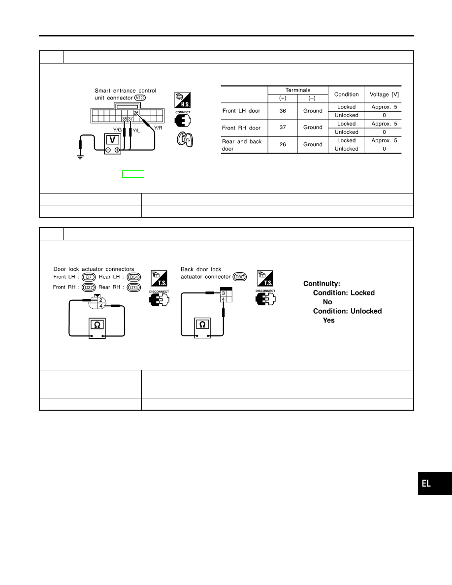
CHECK DOOR UNLOCK SENSOR INPUT SIGNAL

Check voltage between smart entrance control unit terminals 26, 36 or 37 and ground.

SEL343X

Refer to wiring diagram in EL-304.

OK or NG

OK

©

Door unlock sensor is OK.

NG

©

GO TO 2.

2

CHECK DOOR UNLOCK SENSOR

1. Disconnect door unlock sensor connector.
2. Check continuity between door unlock sensor terminals.

SEL344X

OK or NG

OK

©

Check the following.

I

Door unlock sensor ground circuit

I

Harness for open or short between smart entrance control unit and door unlock sensor

NG

©

Replace door unlock sensor.

GI

MA

EM

LC

EC

FE

AT

TF

PD

AX

SU

BR

ST

RS

BT

HA

SC

IDX

THEFT WARNING SYSTEM

Trouble Diagnoses (Cont’d)

EL-313

FRONT DOOR KEY CYLINDER SWITCH CHECK

=NBEL0123S07

1

CHECK DOOR KEY CYLINDER SWITCH INPUT SIGNAL (LOCK/UNLOCK SIGNAL)

Check voltage between smart entrance control unit terminals 30 or 41 and ground.

SEL312X

Refer to wiring diagram in EL-303.

OK or NG

OK

©

Door key cylinder switch LH is OK.

NG

©

GO TO 2.

2

CHECK DOOR KEY CYLINDER SWITCH

1. Disconnect door key cylinder switch LH connector.
2. Check continuity between door key cylinder switch LH terminals.

SEL313X

OK or NG

OK

©

Check the following.

I

Door key cylinder switch LH ground circuit

I

Harness for open or short between smart entrance control unit and door key cylinder
switch LH

NG

©

Replace door key cylinder switch LH.

THEFT WARNING SYSTEM

Trouble Diagnoses (Cont’d)

EL-314

BACK DOOR KEY CYLINDER SWITCH CHECK

=NBEL0123S08

1

CHECK BACK DOOR KEY CYLINDER SWITCH INPUT SIGNAL (LOCK/UNLOCK SIGNAL)

Check voltage between smart entrance control unit terminals 30, 41 or 42 and ground.

SEL314X

Refer to wiring diagram in EL-304.

OK or NG

OK

©

Back door key cylinder switch is OK.

NG

©

GO TO 2.

2

CHECK BACK DOOR KEY CYLINDER SWITCH

1. Disconnect back door key cylinder switch connector.
2. Check continuity between back door key cylinder switch terminals.

SEL345X

OK or NG

OK

©

Check the following.

I

Back door key cylinder switch ground circuit

I

Harness for open or short between smart entrance control unit and back door key cyl-
inder switch

NG

©

Replace back door key cylinder switch.

GI

MA

EM

LC

EC

FE

AT

TF

PD

AX

SU

BR

ST

RS

BT

HA

SC

IDX

THEFT WARNING SYSTEM

Trouble Diagnoses (Cont’d)

EL-315

HORN ALARM CHECK

=NBEL0123S09

1

CHECK HORN ALARM OPERATION

1. Disconnect smart entrance control unit connector.
2. Apply ground to smart entrance control unit terminal 19.

SEL346X

Refer to wiring diagram in EL-304.

OK or NG

OK

©

Horn alarm is OK.

NG

©

GO TO 2.

2

CHECK HORN RELAY

Check horn relay.

OK or NG

OK

©

GO TO 3.

NG

©

Replace horn relay.

3

CHECK POWER SUPPLY FOR HORN RELAY

1. Disconnect horn relay connector.
2. Check voltage between terminal 2 and ground.

SEL347X

OK or NG

OK

©

GO TO 4.

NG

©

Check the following.

I

7.5A fuse (No. 52, located in the fuse and fusible link box)

I

Harness for open or short between horn relay and fuse

THEFT WARNING SYSTEM

Trouble Diagnoses (Cont’d)

EL-316


Content   ..  372  373  374  375   ..