Infiniti QX4 (R50). Manual - part 365
Trouble Diagnoses
NBEL0115
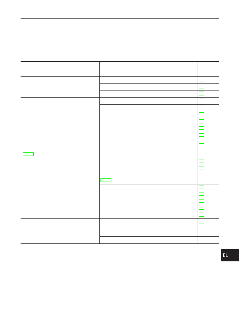
SYMPTOM CHART
NBEL0115S01
NOTE:
I
Always check remote controller battery before replacing
remote controller.
I
The panic alarm operation of multi-remote control system does
not activate with the ignition key inserted in the ignition key
cylinder.
Symptom
Diagnoses/service procedure
Reference
page
(EL-
)
All function of multi-remote control system do not
operate.
1. Remote controller battery check
2. Power supply and ground circuit for control unit check
3. Replace romote controller. Refer to ID Code Entry Procedure. 291
The new ID of remote controller cannot be
entered.
1. Remote controller battery check
2. Key switch (insert) check
3. Door switch check
4. Door lock/unlock switch LH check
5. Power supply and ground circuit for control unit check
6. Replace romote controller. Refer to ID Code Entry Procedure. 291
Door lock or unlock does not function.
(If the power door lock system does not operate
manually, check power door lock system. Refer to
EL-261.)
1. Replace remote controller. Refer to ID Code Entry Procedure. 291
Hazard and horn reminder does not activate prop-
erly when pressing lock or unlock button of remote
controller.
1. Harzard reminder check
2. Horn reminder check*
*: Horn chirp can be activated or deactivated.
First check the horn chirp setting. Refer to “System Description”,
EL-270.
3. Door switch check
4. Replace remote controller. Refer to ID Code Entry Procedure. 291
Interior lamp operation does not activate properly.
1. Interior room lamp operation check
2. Door switch check
3. Front LH door unlock sensor check
Panic alarm (horn and headlamp) does not acti-
vate when panic alarm button is continuously
pressed.
1. Theft warning operation check. Refer to “PRELIMINALY
CHECK” in “THEFT WARNING SYSTEM”.
2. Key switch (insert) check
3. Replace remote controller. Refer to ID Code Entry Procedure. 291
GI
MA
EM
LC
EC
FE
AT
TF
PD
AX
SU
BR
ST
RS
BT
HA
SC
IDX
MULTI-REMOTE CONTROL SYSTEM
Trouble Diagnoses
EL-277