Infiniti QX4 (R50). Manual - part 358
 

  Index      Infiniti     Infiniti QX4 (R50) - service repair manual 2001 year


Search            copyright infringement  


Content   ..  356  357  358  359   ..


Infiniti QX4 (R50). Manual - part 358


MEL847L

GI

MA

EM

LC

EC

FE

AT

TF

PD

AX

SU

BR

ST

RS

BT

HA

SC

IDX

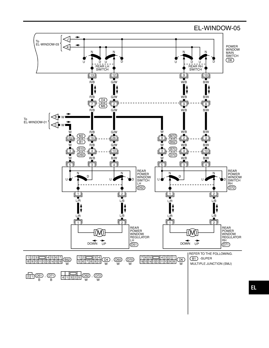
POWER WINDOW

Wiring Diagram — WINDOW — (Cont’d)

EL-249

Trouble Diagnoses

NBEL0221

Symptom

Possible cause

Repair order

None of the power windows can be
operated using any switch.

1. 7.5A fuse, 40A fusible link
2. M145 circuit breaker
3. Power window relay
4. M145 circuit breaker circuit
5. Power window relay circuit
6. Ground circuit
7. Power window main switch

1. Check 7.5A fuse [No. 11, located in fuse block

(J/B)], 40A fusible link (letter f, located in fuse and
fusible link box).

2. Check M145 circuit breaker.
3. Check power window relay.
4. Check the following.
a. Harness between M145 circuit breaker and 40A fus-

ible link

b. Harness between M145 circuit breaker and front

power window main switch

5. Check the following.
a. Harness between 7.5A fuse and power window relay
b. Harness between M145 circuit breaker and power

window relay

6. Check the following.
a. Ground circuit of power window main switch terminal

5

b. Power window relay ground circuit
7. Check power window main switch.

Driver side power window cannot
be operated but other windows can
be operated.

1. Driver side power window regu-

lator circuit

2. Driver side power window regu-

lator

3. Power window main switch

1. Check harness between power window main switch

and driver side power window regulator for open or
short circuit.

2. Check driver side power window regulator.
3. Check power window main switch.

Passenger side power window can-
not be operated but other window
can be operated.

1. Power supply for front power

window switch RH

2. Front power window switch RH

ground circuit

3. Front power window switch RH

circuit

4. Front power window regulator

RH circuit

5. Front power window regulator

RH

6. Front power window main

switch

7. Front power window switch RH

1. Check power supply for front power window switch

RH terminals 6 and 13.

2. Check front power window switch RH ground circuit.
3. Check harness between front power window switch

RH and power window main switch.

4. Check harness between front power window switch

RH and front power window regulator RH for open
or short circuit.

5. Check front power window regulator RH.
6. Check front power window main switch.
7. Check front power window switch RH.

One or more rear power windows
except front window cannot be
operated.

1. Rear power window switches
2. Rear power window regulators
3. Power window main switch
4. Rear power window circuit

1. Check rear power window switches.
2. Check rear power window regulator.
3. Check power window main switch.
4. Check the following.
a. Harness between the rear power window switches

terminal 5 and power window relay

b. Harnesses between power window main switch and

rear power window switches for open/short circuit

c. Harnesses between rear power window switches

and rear power window regulator for open/short cir-
cuit

Power windows except driver’s
side window cannot be operated
using power window main switch
but can be operated by power win-
dow switches.

1. Power window main switch

1. Check power window main switch.

Driver side power window auto-
matic operation does not function
properly.

1. Power window main switch
2. Encoder and limit switch

1. Check power window main switch.
2. Check encoder and limit switch. (EL-252)

POWER WINDOW

Trouble Diagnoses

EL-250

Symptom

Possible cause

Repair order

Front passenger side power win-
dow automatic operation does not
function properly.

1. Front power window switch RH
2. Encoder and limit switch

1. Check front power window switch RH.
2. Check encoder and limit switch. (EL-252)

Retained power operation does not
operate properly.

1. RAP signal circuit
2. Driver or passenger side door

switch circuit

3. Smart entrance control unit

1. Check harness between power window relay termi-

nal 2 and smart entrance control unit terminal 5 for
open or short circuit.

2. Check the following.
a. Harness between smart entrance control unit and

driver or passenger side door switch for short circuit

b. Driver or passenger side door switch ground circuit
c. Driver or passenger side door switch
3. Check smart entrance control unit. (EL-324)

GI

MA

EM

LC

EC

FE

AT

TF

PD

AX

SU

BR

ST

RS

BT

HA

SC

IDX

POWER WINDOW

Trouble Diagnoses (Cont’d)

EL-251

ENCODER AND LIMIT SWITCH CHECK

=NBEL0221S01

1

CHECK DOOR WINDOW SLIDE MECHANISM

Check the following.

I

Obstacles in window, glass molding, etc.

I

Worn or deformed glass molding

I

Door sash tilted too far inward or outward

I

Door window regulator

OK or NG

OK

©

GO TO 2.

NG

©

Remove obstacles or repair door window slide mechanism.

2

CHECK POWER SUPPLY TO LIMIT SWITCH

1. Disconnect front power window regulator LH or RH harness connector.
2. Check voltage between front power window main switch terminal 15 or front power window switch RH terminal 16 and

ground.

SEL725WA

OK or NG

OK

©

GO TO 3.

NG

©

Replace power window main switch or front power window switch RH.

3

CHECK LIMIT SWITCH OPERATION

1. Connect front power window regulator LH or RH harness connector.
2. Check voltage between front power window main switch terminal 15 or front power window switch RH terminal 16 and

ground during power window closing operation.

SEL726WA

OK or NG

OK

©

GO TO 5.

NG

©

GO TO 4.

POWER WINDOW

Trouble Diagnoses (Cont’d)

EL-252


Content   ..  356  357  358  359   ..