Infiniti QX4 (R50). Manual - part 310
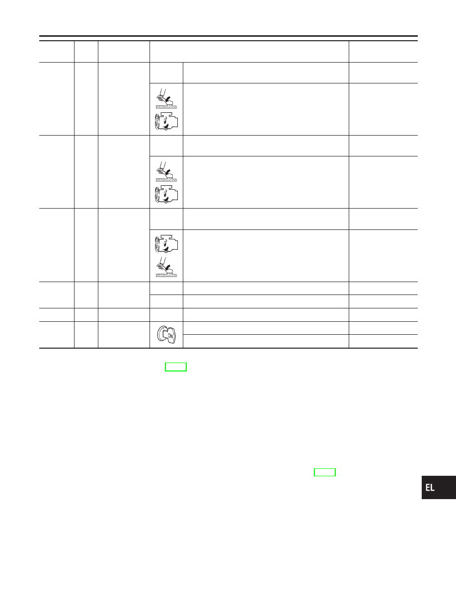
Terminal
No.
Wire
color
Item
Condition
Voltage
(Approximate values)
7
L/R
RH hi beam
When lighting switch is turned to the 2ND position with
“HI BEAM” position
Battery voltage
When releasing parking brake with engine running and
turning lighting switch to “OFF” (daytime light operation)
CAUTION:
Block wheels and ensure selector lever is in N or P
position.
Approx. half battery
voltage
9
PU
RH hi beam
(ground)
When lighting switch is turned to the 2ND position with
“HI BEAM” position
Less than 1V
When releasing parking brake with engine running and
turning lighting switch to “OFF” (daytime light operation)
CAUTION:
Block wheels and ensure selector lever is in N or P
position.
Approx. half battery
voltage
10
GY
LH hi beam
(ground)
When lighting switch is turned to the 2ND position with
“HI BEAM” position
Less than 1V
When releasing parking brake with engine running and
turning lighting switch to “OFF” (daytime light operation)
CAUTION:
Block wheels and ensure selector lever is in N or P
position.
Approx. half battery
voltage
13
14
L/W
W/R
Lighting switch
(Hi beam)
When turning lighting switch to “HI BEAM”
Battery voltage
When turning lighting switch to “FLASH TO PASS”
Battery voltage
16
B
Ground
—
—
17
L/G
Parking brake
switch
When parking brake is released
Battery voltage
When parking brake is set
Less than 1.5V
BATTERY SAVER CONTROL UNIT INSPECTION TABLE
NBEL0193S02
Refer to “HEADLAMP (FOR USA)”, EL-42.
Bulb Replacement
NBEL0194
Refer to “HEADLAMP (FOR USA)” (EL-43).
GI
MA
EM
LC
EC
FE
AT
TF
PD
AX
SU
BR
ST
RS
BT
HA
SC
IDX
HEADLAMP (FOR CANADA) — DAYTIME LIGHT SYSTEM —
Trouble Diagnoses (Cont’d)
EL-57