Infiniti QX4 (R50). Manual - part 307


  Index      Infiniti     Infiniti QX4 (R50) - service repair manual 2001 year


Search            copyright infringement  


Content   ..  305  306  307  308   ..


Infiniti QX4 (R50). Manual - part 307


SEL376X

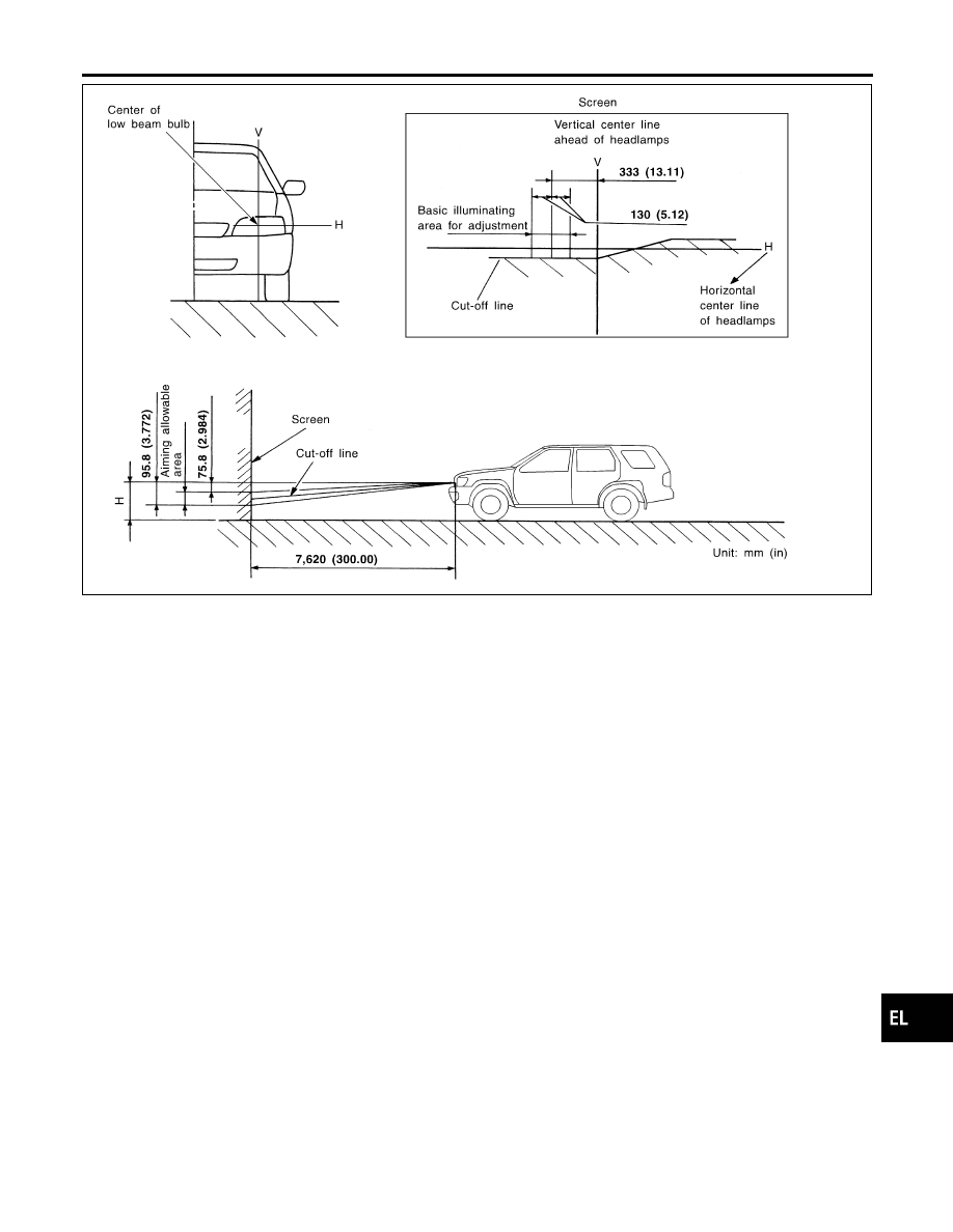
If the vehicle front body has been repaired and/or the headlamp
assembly has been replaced, check aiming. Use the aiming chart
shown in the figure.

I

Basic illuminating area for adjustment should be within
the range shown on the aiming chart. Adjust headlamps
accordingly.

GI

MA

EM

LC

EC

FE

AT

TF

PD

AX

SU

BR

ST

RS

BT

HA

SC

IDX

HEADLAMP (FOR USA) — XENON TYPE —

Aiming Adjustment (Cont’d)

EL-45

Component Parts and Harness Connector
Location

NBEL0161

SEL460X

System Description

NBEL0192

The headlamp system for Canada vehicles contains a daytime light control unit that activates the high beam
headlamps at approximately half illumination whenever the engine is running. If the parking brake is applied
before the engine is started the daytime lights will not be illuminated. The daytime lights will illuminate once
the parking brake is released. Thereafter, the daytime lights will continue to operate when the parking brake
is applied.
And battery saver system is controlled by the headlamp battery saver control unit and smart entrance control
unit.
Power is supplied at all times

I

to headlamp LH relay terminals 1 and 3

I

through 15A fuse (No. 60, located in the fuse and fusible link box), and

I

to headlamp LH relay terminal 6

I

through 20A fuse (No. 32, located in the fuse and fusible link box), and

I

to headlamp RH relay terminals 1 and 3

I

through 15A fuse (No. 59, located in the fuse and fusible link box), and

I

to headlamp RH relay terminal 6

I

through 20A fuse (No. 31, located in the fuse and fusible link box), and

I

to headlamp battery saver control unit terminal 7, and

I

to smart entrance control unit terminal 10

I

through 7.5A fuse [No. 24, located in the fuse block (J/B)].

Ground is supplied

I

to daytime light control unit terminal 16,

I

to auto light control unit terminal 5 and

I

to headlamp battery saver control unit terminals 4 and 11.

When the ignition switch is in the ON or START position, power is also supplied

HEADLAMP (FOR CANADA) — DAYTIME LIGHT SYSTEM —

Component Parts and Harness Connector Location

EL-46

I

to daytime light control unit terminal 3,

I

to auto light control unit terminal 1,

I

to headlamp battery saver control unit terminal 10, and

I

to smart entrance control unit terminal 33

I

through 7.5A fuse [No. 11, located in the fuse block (J/B)], and

I

to headlamp battery saver control unit terminal 1

I

through 10A fuse [No. 16, located in the fuse block (J/B)].

When the ignition switch is in the START position, power is supplied

I

to daytime light control unit terminal 2

I

through 7.5A fuse [No. 26, located in the fuse block (J/B)].

When the ignition switch is in the ACC or ON position, power is supplied

I

to auto light control unit terminal 2

I

through 10A fuse [No. 9, located in the fuse block (J/B)].

HEADLAMP OPERATION

NBEL0192S01

Power Supply to Low Beam and High Beam

NBEL0192S0101

When lighting switch is in 2ND or PASS position, ground is supplied

I

to headlamp relay (LH and RH) terminal 2 from headlamp battery saver control unit terminals 2 and 8

I

through headlamp battery saver control unit terminal 3 and 9

I

from lighting switch terminal 12.

Headlamp relays (LH and RH) are energized.

Low Beam Operation

NBEL0192S0102

When the lighting switch is turned to 2ND and LOW (“B”) positions, power is supplied

I

from terminal 7 of each headlamp relay

I

to terminal 3 of each headlamp

Ground is supplied

I

to terminal 4 of each headlamp

I

through body grounds E13 and E41.

With power and ground supplied, the low beam headlamps illuminate.

High Beam Operation/Flash-to-pass Operation

NBEL0192S0103

When the lighting switch is turned to 2ND and HIGH (“A”) or PASS (“C”) positions, power is supplied

I

to terminal 1 of headlamp LH

I

through daytime light control unit terminals 6 and 5

I

from headlamp LH relay terminal 5

I

to terminal 1 of headlamp RH

I

through daytime light control unit terminals 7 and 4

I

from headlamp RH relay terminal 5, and

I

to combination meter terminal 26 for HIGH BEAM indicator

I

from headlamp LH relay terminal 5.

Ground is supplied

I

to terminal 2 of LH headlamp

I

through daytime light control unit terminals 10 and 13, and

I

to combination meter terminal 27 for the HIGH BEAM indicator

I

through lighting switch terminals 6 and 5

I

through body grounds E13 and E41, and

I

to terminal 2 of RH headlamp

I

through daytime light control unit terminals 9 and 14

I

through lighting switch terminals 9 and 8

I

through body grounds E13 and E41.

With power and ground supplied, the high beam headlamps and HIGH BEAM indicator illuminate.

GI

MA

EM

LC

EC

FE

AT

TF

PD

AX

SU

BR

ST

RS

BT

HA

SC

IDX

HEADLAMP (FOR CANADA) — DAYTIME LIGHT SYSTEM —

System Description (Cont’d)

EL-47

BATTERY SAVER CONTROL

NBEL0192S02

When the ignition switch is turned from ON (or START) to OFF (or ACC) positions while headlamps are
illuminated, The RAP signal is supplied to terminal 10 of the headlamp battery saver control unit from smart
entrance control unit terminal 5.
After counting 45 seconds by the RAP signal from the smart entrance control unit to headlamp battery saver
control unit, the ground supply to terminal 2 of headlamp LH and RH relays from headlamp battery saver con-
trol unit terminals 2 and 8 is terminated.
Then headlamps are turned off.
The headlamps are turned off when LH or RH door is opened even if 45 seconds have not passed after the
ignition switch is turned from ON (or START) to OFF (or ACC) positions while headlamps are illuminated.
When the lighting switch is turned from OFF to 2ND after headlamps are turned to off by the battery saver
control, ground is supply

I

to headlamp battery saver control unit terminals 5 and 13 from lighting switch terminal 11, and

I

to headlamp LH and RH relays terminal 2 from headlamp battery saver control unit terminals 2 and 8

I

through headlamp battery saver control unit terminals 3 and 9, and

I

through lighting switch terminal 12.

Then headlamps illuminate again.

AUTO LIGHT OPERATION

NBEL0192S03

For auto light operation, refer to “HEADLAMP” (EL-33).

DAYTIME LIGHT OPERATION

NBEL0192S04

With the engine running, the lighting switch in the OFF or 1ST position and parking brake released, power is
supplied

I

through daytime light control unit terminals 3 and 7

I

to terminal 1 of RH headlamp

I

through terminal 2 of RH headlamp

I

to daytime light control unit terminal 9

I

through daytime light control unit terminal 6

I

to terminal 1 of LH headlamp.

Ground is supplied to terminal 2 of LH headlamp.

I

through daytime light control unit terminals 10 and 16

I

through body grounds E13 and E41.

Because the high beam headlamps are now wired in series, they operate at half illumination.

HEADLAMP (FOR CANADA) — DAYTIME LIGHT SYSTEM —

System Description (Cont’d)

EL-48


Content   ..  305  306  307  308   ..