Infiniti QX4 (R50). Manual - part 294


  Index      Infiniti     Infiniti QX4 (R50) - service repair manual 2001 year


Search            copyright infringement  


Content   ..  292  293  294  295   ..


Infiniti QX4 (R50). Manual - part 294


ECM Terminals and Reference Value

NBEC0690

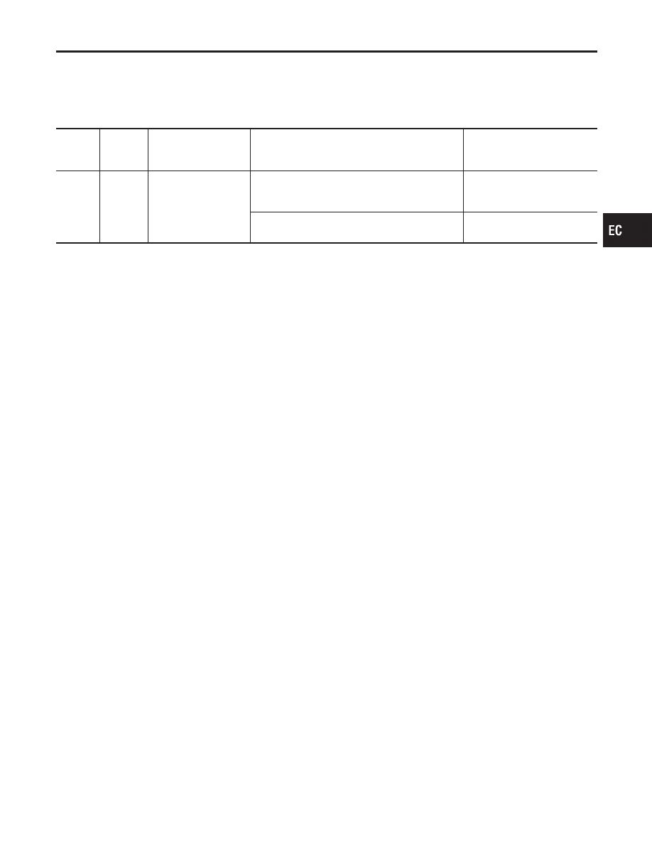
Specification data are reference values and are measured between each terminal and ground.

CAUTION:

Do not use ECM ground terminals when measuring input/output voltage. Doing so may result in dam-
age to the ECM’s transistor. Use a ground other than ECM terminals, such as the ground.

TERMI-

NAL

NO.

WIRE

COLOR

ITEM

CONDITION

DATA (DC Voltage)

52

PU

Electrical load signal

[Engine is running]

I

Rear window defogger: ON

I

Hi-beam headlamp: ON

BATTERY VOLTAGE
(11 - 14V)

[Engine is running]

I

Electrical load: OFF

0V

GI

MA

EM

LC

FE

AT

TF

PD

AX

SU

BR

ST

RS

BT

HA

SC

EL

IDX

ELECTRICAL LOAD SIGNAL

ECM Terminals and Reference Value

EC-643

Wiring Diagram

NBEC0604

MEC421D

ELECTRICAL LOAD SIGNAL

Wiring Diagram

EC-644

Diagnostic Procedure

NBEC0605

1

CHECK LOAD SIGNAL CIRCUIT OVERALL FUNCTION-I

1. Turn ignition switch “ON”.
2. Check voltage between ECM terminal 52 and ground under the following conditions.

SEF610X

OK or NG

OK

©

GO TO 2.

NG

©

GO TO 3.

2

CHECK LOAD SIGNAL CIRCUIT OVERALL FUNCTION-II

Check voltage between ECM terminal 52 and ground under the following conditions.

SEF611X

OK or NG

OK

©

INSPECTION END

NG

©

GO TO 7.

3

CHECK REAR WINDOW DEFOGGER FUNCTION

1. Start engine.
2. Turn “ON” the rear window defogger switch.
3. Check the rear windshield. Is the rear windshield heated up?

Yes or No

Yes

©

GO TO 4.

No

©

Refer to EL-151, “Rear Window Defogger”.

GI

MA

EM

LC

FE

AT

TF

PD

AX

SU

BR

ST

RS

BT

HA

SC

EL

IDX

ELECTRICAL LOAD SIGNAL

Diagnostic Procedure

EC-645

4

CHECK REAR WINDOW DEFOGGER INPUT SIGNAL CIRCUIT FOR OPEN OR SHORT

1. Stop engine.
2. Disconnect ECM harness connector.
3. Disconnect rear window defogger relay.
4. Check harness continuity between ECM terminal 52 and rear window defogger relay terminals 7.

SEF031Z

5. Also check harness for short to ground and short to power.

OK or NG

OK

©

GO TO 6.

NG

©

GO TO 5.

5

DETECT MALFUNCTIONING PART

Check the following.

I

Harness connectors E1, M1

I

Harness connectors M33, F22

I

Diode M37

I

Harness for open and short between ECM and rear window defigger relay

©

Repair open circuit or short to ground or short to power in harness or connectors.

6

CHECK INTERMITTENT INCIDENT

Perform “TROUBLE DIAGNOSIS FOR INTERMITTENT INCIDENT”, EC-140.

©

INSPECTION END

7

CHECK HEADLAMP FUNCTION

1. Start engine.
2. Turn the lighting switch “ON” at 1st position with high beam.
3. Check that headlamps are illuminated.

OK or NG

OK

©

GO TO 8.

NG

©

Refer to EL-60, “HEADLAMP (FOR USA)” or EL-123, “HEADLAMP (FOR CANADA) —
DAYTIME LIGHT SYSTEM”.

ELECTRICAL LOAD SIGNAL

Diagnostic Procedure (Cont’d)

EC-646


Content   ..  292  293  294  295   ..