Infiniti QX4 (R50). Manual - part 266


  Index      Infiniti     Infiniti QX4 (R50) - service repair manual 2001 year


Search            copyright infringement  


Content   ..  264  265  266  267   ..


Infiniti QX4 (R50). Manual - part 266


5

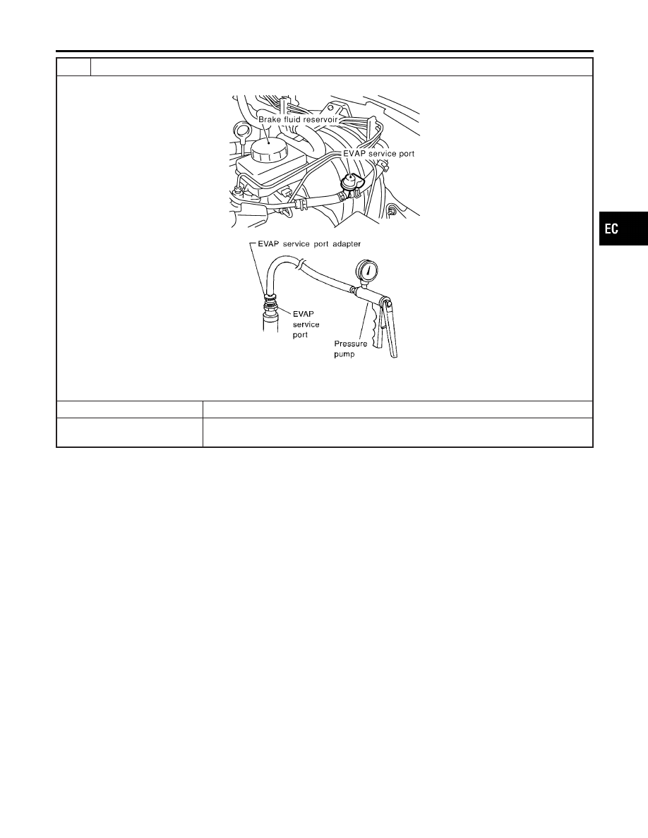
INSTALL THE PRESSURE PUMP

To locate the EVAP leak, install EVAP service port adapter and pressure pump to EVAP service port securely.

SEF983Y

SEF916U

NOTE:
Improper installation of the EVAP service port adapter to the EVAP service port may cause leaking.

Models with CONSULT-II

©

GO TO 6.

Models without CON-
SULT-II

©

GO TO 7.

GI

MA

EM

LC

FE

AT

TF

PD

AX

SU

BR

ST

RS

BT

HA

SC

EL

IDX

DTC P1441 EVAP CONTROL SYSTEM (VERY SMALL LEAK)

Diagnostic Procedure (Cont’d)

EC-531

6

CHECK FOR EVAP LEAK

With CONSULT-II

1. Turn ignition switch “ON”.
2. Select “EVAP SYSTEM CLOSE” of “WORK SUPPORT” mode with CONSULT-II.
3. Touch “START” and apply pressure into the EVAP line until the pressure indicator reaches the middle of the bar graph.

NOTE:

I

Never use compressed air or a high pressure pump.

I

Do not exceed 4.12 kPa (0.042 kg/cm

2

, 0.6 psi) of pressure in the system.

PEF917U

4. Using EVAP leak detector, locate the EVAP leak. For the leak detector, refer to the instruction manual for more details.

Refer to “EVAPORATIVE EMISSION LINE DRAWING”, EC-36.

SEF200U

OK or NG

OK

©

GO TO 8.

NG

©

Repair or replace.

DTC P1441 EVAP CONTROL SYSTEM (VERY SMALL LEAK)

Diagnostic Procedure (Cont’d)

EC-532

7

CHECK FOR EVAP LEAK

Without CONSULT-II

1. Turn ignition switch “OFF”.
2. Apply 12 volts DC to EVAP canister vent control valve. The valve will close. (Continue to apply 12 volts until the end of

test.)

SEF598U

3. Apply 12 volts DC to vacuum cut valve bypass valve. The valve will open. (Continue to apply 12V until the end of test.)

SEF599U

4. Pressurize the EVAP line using pressure pump with 1.3 to 2.7 kPa (10 to 20 mmHg, 0.39 to 0.79 inHg), then remove

pump and EVAP service port adapter.
NOTE:

I

Never use compressed air or a high pressure pump.

I

Do not exceed 4.12 kPa (0.042 kg/cm

2

, 0.6 psi) of pressure in the system.

5. Using EVAP leak detector, locate the EVAP leak. For the leak detector, refer to the instruction manual for more details.

Refer to “EVAPORATIVE EMISSION LINE DRAWING”, EC-36.

SEF200U

OK or NG

OK

©

GO TO 8.

NG

©

Repair or replace.

GI

MA

EM

LC

FE

AT

TF

PD

AX

SU

BR

ST

RS

BT

HA

SC

EL

IDX

DTC P1441 EVAP CONTROL SYSTEM (VERY SMALL LEAK)

Diagnostic Procedure (Cont’d)

EC-533

8

CHECK WATER SEPARATOR

1. Check visually for insect nests in the water separator air inlet.
2. Check visually for cracks or flaws in the appearance.
3. Check visually for cracks or flaws in the hose.
4. Check that and are not clogged by blowing air into with A, and then plugged.

SEF829T

5. In case of NG in items 2 - 4, replace the parts.
NOTE:

I

Do not disassemble water separator.

OK or NG

OK

©

GO TO 9.

NG

©

Replace water separator.

9

CHECK EVAP CANISTER VENT CONTROL VALVE, O-RING AND CIRCUIT

Refer to “DTC Confirmation Procedure”, EC-375.

OK or NG

OK

©

GO TO 10.

NG

©

Repair or replace EVAP canister vent control valve and O-ring or harness/connector.

10

CHECK IF EVAP CANISTER SATURATED WITH WATER

1. Remove EVAP canister with EVAP canister vent control valve attached.
2. Does water drain from the EVAP canister?

SEF596U

Yes or No

Yes

©

GO TO 11.

No (With CONSULT-II)

©

GO TO 13.

No (Without CONSULT-
II)

©

GO TO 14.

DTC P1441 EVAP CONTROL SYSTEM (VERY SMALL LEAK)

Diagnostic Procedure (Cont’d)

EC-534


Content   ..  264  265  266  267   ..