Infiniti QX4 (R50). Manual - part 265


  Index      Infiniti     Infiniti QX4 (R50) - service repair manual 2001 year


Search            copyright infringement  


Content   ..  263  264  265  266   ..


Infiniti QX4 (R50). Manual - part 265


I

EVAP purge line rubber tube bent.

I

Blocked or bent rubber tube to EVAP control system pressure
sensor

I

Loose or disconnected rubber tube

I

EVAP canister vent control valve and the circuit

I

EVAP canister purge volume control solenoid valve

I

Absolute pressure sensor

I

Fuel tank temperature sensor

I

O-ring of EVAP canister vent control valve is missing or dam-
aged.

I

Water separator

I

EVAP canister is saturated with water.

I

Fuel level sensor and the circuit

I

EVAP control system pressure sensor

SEF881X

SEF882X

SEF883X

DTC Confirmation Procedure

NBEC0317

CAUTION:

Never remove fuel filler cap during the DTC confirmation pro-
cedure.
NOTE:

I

If DTC P1441 is displayed with P0440, perform TROUBLE
DIAGNOSIS FOR DTC P1441 first.

I

If “DIAGNOSTIC TROUBLE CODE CONFIRMATION PRO-
CEDURE” has been previously conducted, always turn
ignition switch “OFF” and wait at least 5 seconds before
conducting the next test.

I

After repair, make sure that the hoses and clips are
installed properly.

TESTING CONDITION:

I

Open engine hood before conducting following proce-
dure.

I

If any of following condition is met just before the DTC
confirmation procedure, leave the vehicle for more than 1
hour.

a)

Fuel filler cap is removed.

b)

Refilled or drained the fuel.

c)

EVAP component parts is/are removed.

I

Before performing the following procedure, confirm that
battery voltage is more than 11V at idle.
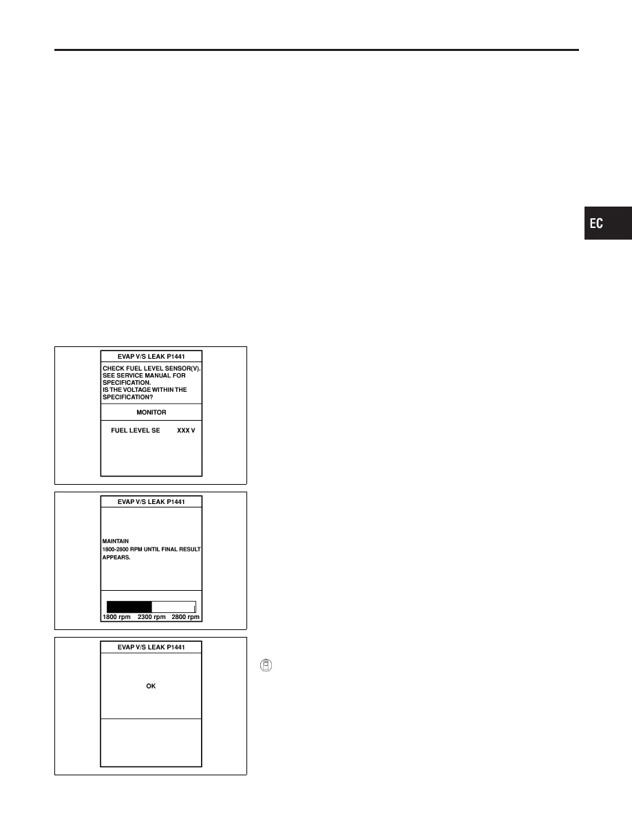
With CONSULT-II

1)

Turn ignition switch “ON” and select “DATA MONITOR” mode
with CONSULT-II.

2)

Make sure the following conditions are met.
FUEL LEVEL SE: 1.08 - 0.2V
COOLAN TEMP/S: 0 - 32°C (32 - 90°F)
FUEL T/TMP SE: 0 - 35°C (32 - 95°F)
INT A/TEMP SE: More than 0°C (32°F)
If NG, turn ignition switch “OFF” and leave the vehicle in a cool

GI

MA

EM

LC

FE

AT

TF

PD

AX

SU

BR

ST

RS

BT

HA

SC

EL

IDX

DTC P1441 EVAP CONTROL SYSTEM (VERY SMALL LEAK)

Possible Cause (Cont’d)

EC-527

place or refilling/draining fuel until the output voltage condition
of the “FUEL LEVEL SE” meets within the range above and
leave the vehicle for more than 1 hour. Then start from step 1).

3)

Turn ignition switch “OFF” and wait at least 5 seconds.

4)

Turn ignition switch “ON”.

5)

Select “EVAP VERY/SML LEAK P1441” of “EVAPORATIVE
SYSTEM” in “DTC WORK SUPPORT” mode with CONSULT-
II.
Follow the instruction displayed.

6)

Make sure that “OK” is displayed.
If “NG” is displayed, refer to “Diagnostic Procedure”, EC-529.

NOTE:

I

If the engine speed cannot be maintained within the range
displayed

on

CONSULT-II

screen,

go

to

“Basic

inspection”, EC-101.

I

Make sure that EVAP hoses are connected to EVAP canis-
ter purge volume control solenoid valve properly.

OVERALL FUNCTION CHECK

NBEC0317S05

With GST

Use this procedure to check the overall function of the EVAP very
small leak function. During this check, a 1st trip DTC might not be
confirmed.

SEF462UA

CAUTION:

I

Never use compressed air, doing so may damage the
EVAP system.

I

Do not start engine.

I

Do not exceeded 4.12 kPa (0.042 kg/cm

2

, 0.6 psi).

1)

Attach the EVAP service port adapter securely to the EVAP
service port.

2)

Set the pressure pump and a hose.

3)

Also set a vacuum gauge via 3-way connector and a hose.

4)

Turn ignition switch “ON”.

5)

Connect GST and select mode 8.

6)

Using mode 8 control the EVAP canister vent control valve
(close) and vacuum cut valve bypass valve (open).

7)

Apply pressure and make sure the following conditions are
satisfied.
Pressure to be applied: 2.7 kPa (20 mmHg, 0.79 inHg)
Time to be waited after the pressure drawn in to the EVAP
system and the pressure to be dropped: 60 seconds and
the pressure should not be dropped more than 0.4 kPa (3
mmHg, 0.12 inHg)
If NG, go to diagnostic procedure, EC-529.

NOTE:
For more information, refer to GST instruction manual.

DTC P1441 EVAP CONTROL SYSTEM (VERY SMALL LEAK)

DTC Confirmation Procedure (Cont’d)

EC-528

Diagnostic Procedure

NBEC0643

1

CHECK FUEL FILLER CAP DESIGN

1. Turn ignition switch “OFF”.
2. Check for genuine NISSAN fuel filler cap design.

SEF915U

OK or NG

OK

©

GO TO 2.

NG

©

Replace with genuine NISSAN fuel filler cap.

2

CHECK FUEL FILLER CAP INSTALLATION

Check that the cap is tightened properly by rotating the cap clockwise.

OK or NG

OK

©

GO TO 3.

NG

©

I

Open fuel filler cap, then clean cap and fuel filler neck threads using air blower.

I

Retighten until ratcheting sound is heard.

3

CHECK FUEL FILLER CAP FUNCTION

Check for air releasing sound while opening the fuel filler cap.

OK or NG

OK

©

GO TO 5.

NG

©

GO TO 4.

GI

MA

EM

LC

FE

AT

TF

PD

AX

SU

BR

ST

RS

BT

HA

SC

EL

IDX

DTC P1441 EVAP CONTROL SYSTEM (VERY SMALL LEAK)

Diagnostic Procedure

EC-529

4

CHECK FUEL TANK VACUUM RELIEF VALVE

1. Wipe clean valve housing.
2. Check valve opening pressure and vacuum.

SEF427N

SEF943S

Pressure:

15.3 - 20.0 kPa (0.156 - 0.204 kg/cm

2

, 2.22 - 2.90 psi)

Vacuum:

−6.0 to −3.3 kPa (−0.061 to −0.034 kg/cm

2

, −0.87 to −0.48 psi)

CAUTION:

Use only a genuine fuel filler cap as a replacement. If an incorrect fuel filler cap is used, the MIL may come on.

OK or NG

OK

©

GO TO 5.

NG

©

Replace fuel filler cap with a genuine one.

DTC P1441 EVAP CONTROL SYSTEM (VERY SMALL LEAK)

Diagnostic Procedure (Cont’d)

EC-530


Content   ..  263  264  265  266   ..