Infiniti QX4 (R50). Manual - part 261
On Board Diagnosis Logic
NBEC0576
Malfunction is detected when
(Malfunction A) 120° signal is not entered to ECM for the first few
seconds during engine cranking,
(Malfunction B) 120° signal is not entered to ECM during engine
running,
(Malfunction C) 120° signal cycle excessively changes during
engine running.
FAIL-SAFE MODE
NBEC0576S01
When the ECM enters the fail-safe mode, the MIL illuminates.
Detected items
Engine operating condition in fail-safe mode
Crankshaft position sensor (REF)
circuit
Compression TDC signal (120° signal) is controlled by camshaft position sensor (PHASE)
signal and crankshaft position sensor (POS) signal. Ignition timing will be delayed 0° to 2°.
Possible Cause
NBEC0577
I
Harness or connectors
(The crankshaft position sensor (REF) circuit is open or
shorted.)
I
Crankshaft position sensor (REF)
I
Starter motor (Refer to SC section.)
I
Starting system circuit (Refer to SC section.)
I
Dead (Weak) battery
DTC Confirmation Procedure
NBEC0578
NOTE:
I
Perform “PROCEDURE FOR MALFUNCTION A” first. If 1st
trip DTC cannot be confirmed, perform “PROCEDURE
FOR MALFUNCTION B AND C”.
I
If
“DTC
Confirmation
Procedure”
has
been
previously
conducted, always turn ignition switch “OFF” and wait at least
10 seconds before conducting the next test.
TESTING CONDITION:
Before performing the following procedure, confirm that bat-
tery voltage is more than 10.5V at idle.
SEF013Y
PROCEDURE FOR MALFUNCTION A
NBEC0578S01
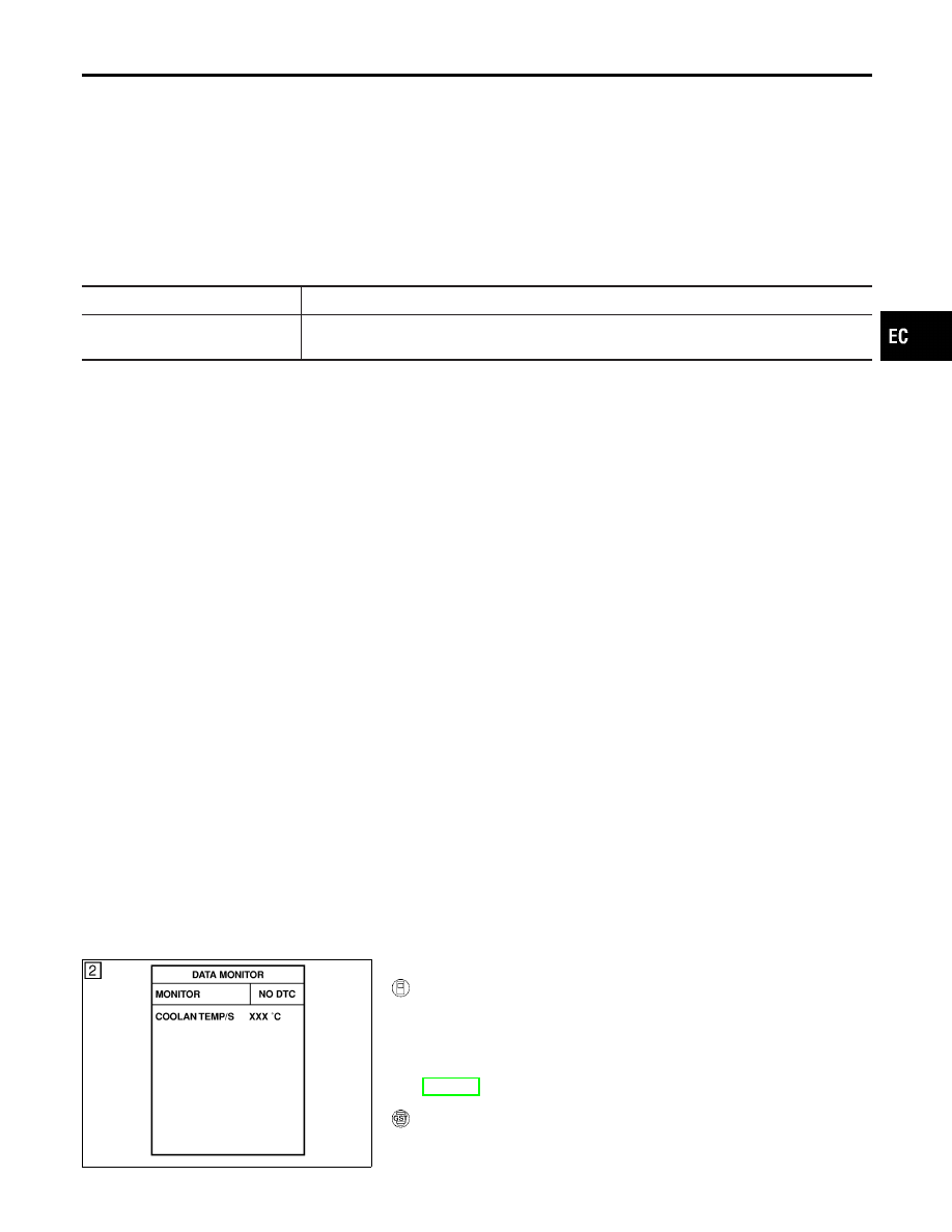
With CONSULT-II
NBEC0578S0101
1)
Turn ignition switch “ON”.
2)
Select “DATA MONITOR” mode with CONSULT-II.
3)
Crank engine for at least 2 seconds.
4)
If 1st trip DTC is detected, go to “Diagnostic Procedure”,
EC-514.
With GST
NBEC0578S0102
Follow the procedure “With CONSULT-II” above.
GI
MA
EM
LC
FE
AT
TF
PD
AX
SU
BR
ST
RS
BT
HA
SC
EL
IDX
DTC P1335 CRANKSHAFT POSITION SENSOR (CKPS) (REF)
On Board Diagnosis Logic
EC-511