Infiniti QX4 (R50). Manual - part 260
10
CHECK CONDENSER GROUND CIRCUIT FOR OPEN AND SHORT
1. Turn ignition switch OFF.
2. Check harness continuity between condenser terminal 2 and engine ground. Refer to Wiring Diagram.
Continuity should exist.
3. Also check harness for short to power.
OK or NG
OK
©
GO TO 11.
NG
©
Repair open circuit or short to power in harness or connectors.
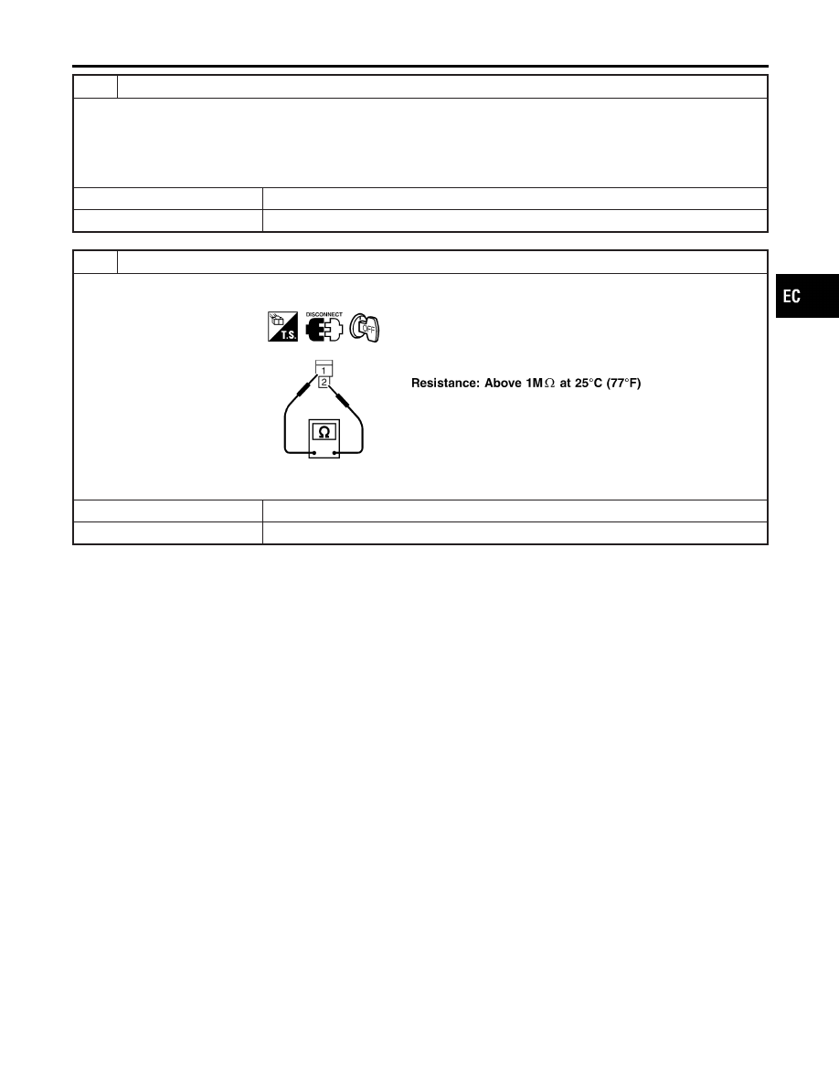
11
CHECK CONDENSER
Check resistance between condenser terminals 1 and 2.
SEF369X
OK or NG
OK
©
GO TO 12.
NG
©
Replace condenser.
GI
MA
EM
LC
FE
AT
TF
PD
AX
SU
BR
ST
RS
BT
HA
SC
EL
IDX
DTC P1320 IGNITION SIGNAL
Diagnostic Procedure (Cont’d)
EC-507