Infiniti QX4 (R50). Manual - part 242


  Index      Infiniti     Infiniti QX4 (R50) - service repair manual 2001 year


Search            copyright infringement  


Content   ..  240  241  242  243   ..


Infiniti QX4 (R50). Manual - part 242


Diagnostic Procedure

NBEC0263

1

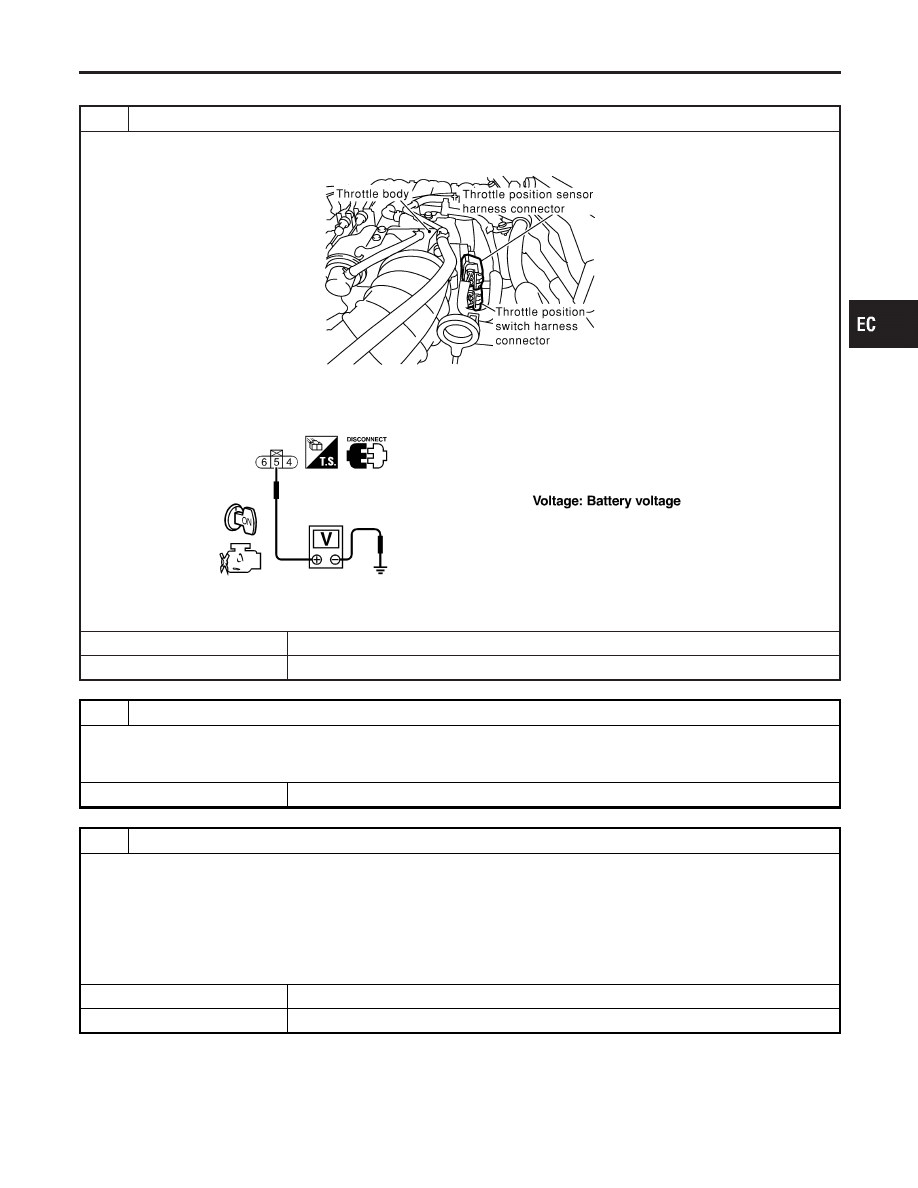
CHECK CLOSED THROTTLE POSITION SWITCH POWER SUPPLY CIRCUIT

1. Turn ignition switch “OFF”.
2. Disconnect throttle position switch harness connector.

SEF944Y

3. Turn ignition switch “ON”.
4. Check voltage between throttle position switch terminal 5 and engine ground with CONSULT-II or tester.

SEF346X

OK or NG

OK

©

GO TO 3.

NG

©

GO TO 2.

2

DETECT MALFUNCTIONING PART

Check the following.

I

Harness connectors M32, F23

I

Harness for open or short between throttle position switch and ECM

©

Repair harness or connectors.

3

CHECK CLOSED THROTTLE POSITION SWITCH INPUT SIGNAL CIRCUIT FOR OPEN AND SHORT

1. Turn ignition switch “OFF”.
2. Disconnect ECM harness connector.
3. Check harness continuity between ECM terminal 56 and throttle position switch terminal 6.

Refer to Wiring Diagram.

Continuity should exist.

4. Also check harness for short to ground and short to power.

OK or NG

OK

©

GO TO 4.

NG

©

Repair open circuit or short to ground or short to power in harness or connectors.

GI

MA

EM

LC

FE

AT

TF

PD

AX

SU

BR

ST

RS

BT

HA

SC

EL

IDX

DTC P0510 CLOSED THROTTLE POSITION SWITCH

Diagnostic Procedure

EC-435

4

CHECK IGNITION TIMING AND ENGINE IDLE SPEED

Check the following items. Refer to “Basic Inspection”, EC-101.

MTBL0656

Models with CONSULT-II

©

GO TO 6.

Models without CON-
SULT-II

©

GO TO 6.

5

CHECK THROTTLE POSITION SWITCH

With CONSULT-II

1. Start engine and warm it up to normal operating temperature.
2. Turn ignition switch “OFF”.
3. Remove vacuum hose connected to throttle opener.
4. Connect suitable vacuum hose to vacuum pump and the throttle opener.
5. Apply vacuum [more than −40.0 kPa (−300 mmHg, −11.81 inHg)] until the throttle drum becomes free from the rod of

the throttle opener.

SEF793W

6. Turn ignition switch “ON”.
7. Select “DATA MONITOR” mode with CONSULT-II.
8. Check indication of “CLSD THL/P SW” under the following conditions.

Measurement must be made with throttle position switch installed in vehicle.

MTBL0355

OK or NG

OK (With CONSULT-II)

©

GO TO 8.

OK (Without CONSULT-
II)

©

GO TO 9.

NG

©

GO TO 7.

DTC P0510 CLOSED THROTTLE POSITION SWITCH

Diagnostic Procedure (Cont’d)

EC-436

6

CHECK THROTTLE POSITION SWITCH

1. Start engine and warm it up to normal operating temperature.
2. Turn ignition switch “OFF”.
3. Remove vacuum hose connected to throttle opener.
4. Connect suitable vacuum hose to vacuum pump and the throttle opener.
5. Apply vacuum [more than −40.0 kPa (−300 mmHg, −11.81 inHg)] until the throttle drum becomes free from the rod of

the throttle opener.

SEF793W

6. Disconnect closed throttle position switch harness connector.
7. Check continuity between closed throttle position switch terminals 6 and 5 under the following conditions.

Resistance measurement must be made with throttle position switch installed in vehicle.

SEF998Y

OK or NG

OK (With CONSULT-II)

©

GO TO 8.

OK (Without CONSULT-
II)

©

GO TO 9.

NG

©

GO TO 7.

GI

MA

EM

LC

FE

AT

TF

PD

AX

SU

BR

ST

RS

BT

HA

SC

EL

IDX

DTC P0510 CLOSED THROTTLE POSITION SWITCH

Diagnostic Procedure (Cont’d)

EC-437

7

ADJUST THROTTLE POSITION SWITCH

Check the following items. Refer to “Basic Inspection”, EC-101.

MTBL0655

Is it possible to adjust closed throttle position switch?

Yes or No

Yes (With CONSULT-II)

©

GO TO 9.

Yes (Without CONSULT-
II)

©

GO TO 9.

No

©

Replace throttle position switch.

8

CHECK THROTTLE POSITION SENSOR

With CONSULT-II

1. Start engine and warm it up to normal operating temperature.
2. Stop engine (ignition switch OFF).
3. Remove the vacuum hose connected to the throttle opener.
4. Connect suitable vacuum hose to the vacuum pump and the opener.
5. Apply vacuum [more than −40.0 kPa (−300 mmHg, −11.81 inHg)] until the throttle drum becomes free from the rod of

the throttle opener.

SEF793W

6. Turn ignition switch ON.
7. Select “DATA MONITOR” mode with CONSULT-II.
8. Check voltage of “THRTL POS SEN” under the following conditins.

Voltage measurement must be made with throttle position sensor installed in vehicle.

MTBL0230

OK or NG

OK

©

GO TO 10.

NG

©

Replace throttle position sensor.

DTC P0510 CLOSED THROTTLE POSITION SWITCH

Diagnostic Procedure (Cont’d)

EC-438


Content   ..  240  241  242  243   ..