Infiniti QX4 (R50). Manual - part 227


  Index      Infiniti     Infiniti QX4 (R50) - service repair manual 2001 year


Search            copyright infringement  


Content   ..  225  226  227  228   ..


Infiniti QX4 (R50). Manual - part 227


Possible Cause

NBEC0512

I

Harness or connectors
(The valve circuit is open or shorted.)

I

EVAP canister vent control valve

DTC Confirmation Procedure

NBEC0232

NOTE:
If “DTC Confirmation Procedure” has been previously conducted,
always turn ignition switch “OFF” and wait at least 10 seconds
before conducting the next test.
TESTING CONDITION:
Before performing the following procedure, confirm battery
voltage is more than 11V at idle.

SEF058Y

WITH CONSULT-II

NBEC0232S01

1)

Turn ignition switch “ON”.

2)

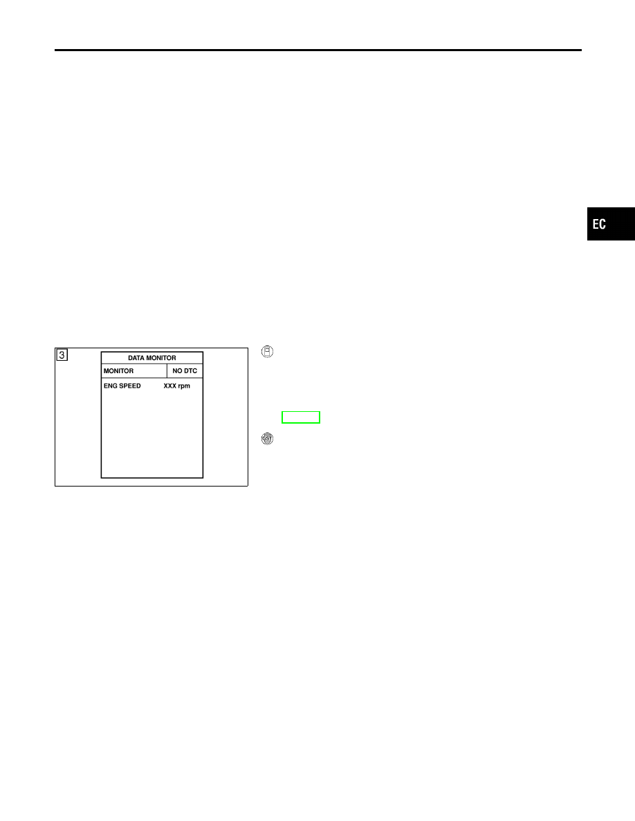
Select “DATA MONITOR” mode with CONSULT-II.

3)

Start engine and wait at least 8 seconds.

4)

If 1st trip DTC is detected, go to “Diagnostic Procedure”,
EC-377.

WITH GST

NBEC0232S02

Follow the procedure “WITH CONSULT-II” above.

GI

MA

EM

LC

FE

AT

TF

PD

AX

SU

BR

ST

RS

BT

HA

SC

EL

IDX

DTC P0446 EVAPORATIVE EMISSION (EVAP) CANISTER VENT CONTROL

VALVE (CIRCUIT)

Possible Cause

EC-375

Wiring Diagram

NBEC0233

MEC963C

DTC P0446 EVAPORATIVE EMISSION (EVAP) CANISTER VENT CONTROL

VALVE (CIRCUIT)

Wiring Diagram

EC-376

Diagnostic Procedure

NBEC0234

1

INSPECTION START

1. Do you have CONSULT-II?

Yes or No

Yes

©

GO TO 2.

No

©

GO TO 3.

2

CHECK EVAP CANISTER VENT CONTROL VALVE CIRCUIT

With CONSULT-II

1. Turn ignition switch “OFF” and then turn “ON”.
2. Select “VENT CONTROL/V” in “ACTIVE TEST” mode with CONSULT-II.
3. Touch “ON/OFF” on CONSULT-II screen.

SEF989Y

4. Check for operating sound of the valve.

Clicking noise should be heard.

OK or NG

OK

©

GO TO 7.

NG

©

GO TO 3.

GI

MA

EM

LC

FE

AT

TF

PD

AX

SU

BR

ST

RS

BT

HA

SC

EL

IDX

DTC P0446 EVAPORATIVE EMISSION (EVAP) CANISTER VENT CONTROL

VALVE (CIRCUIT)

Diagnostic Procedure

EC-377

3

CHECK EVAP CANISTER VENT CONTROL VALVE POWER SUPPLY CIRCUIT

1. Turn ignition switch “OFF”.
2. Disconnect EVAP canister vent control valve harness connector.

SEF143S

3. Turn ignition switch “ON”.
4. Check voltage between EVAP canister vent control valve terminal 2 and ground with CONSULT-II or tester.

SEF990Y

OK or NG

OK

©

GO TO 5.

NG

©

GO TO 4.

4

DETECT MALFUNCTIONING PART

Check the following.

I

Harness connectors M2, B1 and B43, B101

I

Fuse block (J/B) connector M10

I

10A fuse

I

Harness for open or short between EVAP canister vent control valve and fuse

©

Repair harness or connectors.

5

CHECK EVAP CANISTER VENT CONTROL VALVE OUTPUT SIGNAL CIRCUIT FOR OPEN AND SHORT

1. Turn ignition switch “OFF”.
2. Disconnect ECM harness connector.
3. Check harness continuity between ECM terminal 40 and EVAP canister vent control valve terminal 1.

Refer to Wiring Diagram.

Continuity should exist.

4. Also check harness for short to ground and short to power.

OK or NG

OK

©

GO TO 7.

NG

©

GO TO 6.

DTC P0446 EVAPORATIVE EMISSION (EVAP) CANISTER VENT CONTROL

VALVE (CIRCUIT)

Diagnostic Procedure (Cont’d)

EC-378


Content   ..  225  226  227  228   ..