Infiniti QX4 (R50). Manual - part 224


  Index      Infiniti     Infiniti QX4 (R50) - service repair manual 2001 year


Search            copyright infringement  


Content   ..  222  223  224  225   ..


Infiniti QX4 (R50). Manual - part 224


17

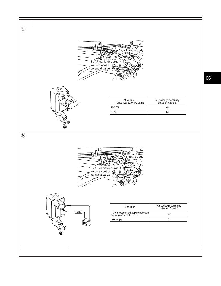
CHECK EVAP CANISTER PURGE VOLUME CONTROL SOLENOID VALVE

With CONSULT-II

Check air passage continuity of EVAP canister purge volume control solenoid valve under the following conditions.

SEF986Y

SEF334X

Without CONSULT-II

Check air passage continuity of EVAP canister purge volume control solenoid valve under the following conditions.

SEF986Y

SEF335X

OK or NG

OK

©

GO TO 18.

NG

©

Replace EVAP canister purge volume control solenoid valve.

GI

MA

EM

LC

FE

AT

TF

PD

AX

SU

BR

ST

RS

BT

HA

SC

EL

IDX

DTC P0440 EVAP CONTROL SYSTEM (SMALL LEAK) (NEGATIVE PRESSURE)

Diagnostic Procedure (Cont’d)

EC-363

18

CHECK ABSOLUTE PRESSURE SENSOR

1. Remove absolute pressure sensor with its harness connector connected.

SEF961Y

2. Remove hose from absolute pressure sensor.
3. Install a vacuum pump to absolute pressure sensor.
4. Turn ignition switch “ON” and check output voltage between ECM terminal 80 and engine ground under the following

conditions.

SEF300XA

CAUTION:

I

Always calibrate the vacuum pump gauge when using it.

I

Do not apply below −93.3 kPa (–700 mmHg, –27.56 inHg) or over 101.3 kPa (760 mmHg, 29.92 inHg) of pressure.

OK or NG

OK

©

GO TO 19.

NG

©

Replace absolute pressure sensor.

19

CHECK FUEL TANK TEMPERATURE SENSOR

1. Remove fuel level sensor unit.
2. Check resistance between fuel level sensor unit and fuel pump terminals 1 and 2 by heating with hot water or heat gun

as shown in the figure.

SEF974Y

OK or NG

OK

©

GO TO 20.

NG

©

Replace fuel level sensor unit.

DTC P0440 EVAP CONTROL SYSTEM (SMALL LEAK) (NEGATIVE PRESSURE)

Diagnostic Procedure (Cont’d)

EC-364

20

CHECK EVAP CONTROL SYSTEM PRESSURE SENSOR

1. Remove EVAP control system pressure sensor with its harness connector connected.

CAUTION:

I

Never apply force to the air hole protector of the sensor if equipped.

SEF799W

2. Remove hose from EVAP control system pressure sensor.
3. Turn ignition switch “ON”.
4. Use pump to apply vacuum and pressure to EVAP control system pressure sensor as shown in figure.

CAUTION:

I

Always calibrate the vacuum pump gauge when using it.

I

Do not apply below −20 kPa (−150 mmHg, −5.91 inHg) or over 20 kPa (150 mmHg, 5.91 inHg) of pressure.

5. Check input voltage between ECM terminal 84 and ground.

SEF342X

CAUTION:

I

Discard and EVAP control system pressure sensor which has been dropped from a height of more than 0.5m
(19.7in) onto a hard surface such as a concrete floor; use a new one.

OK or NG

OK

©

GO TO 21.

NG

©

Replace EVAP control system pressure sensor.

21

CHECK EVAP PURGE LINE

Check EVAP purge line (pipe, rubber tube, fuel tank and EVAP canister) for cracks or improper connection.
Refer to “Evaporative Emission System”, EC-32.

OK or NG

OK

©

GO TO 22.

NG

©

Repair or reconnect the hose.

22

CLEAN EVAP PURGE LINE

Clean EVAP purge line (pipe and rubber tube) using air blower.

©

GO TO 23.

GI

MA

EM

LC

FE

AT

TF

PD

AX

SU

BR

ST

RS

BT

HA

SC

EL

IDX

DTC P0440 EVAP CONTROL SYSTEM (SMALL LEAK) (NEGATIVE PRESSURE)

Diagnostic Procedure (Cont’d)

EC-365

23

CHECK FUEL LEVEL SENSOR

Refer to EL-108, “Fuel Level Sensor Unit Check”.

OK or NG

OK

©

GO TO 24.

NG

©

Replace fuel level sensor unit.

24

CHECK INTERMITTENT INCIDENT

Refer to “TROUBLE DIAGNOSIS FOR INTERMITTENT INCIDENT”, EC-140.

©

INSPECTION END

DTC P0440 EVAP CONTROL SYSTEM (SMALL LEAK) (NEGATIVE PRESSURE)

Diagnostic Procedure (Cont’d)

EC-366


Content   ..  222  223  224  225   ..