Infiniti QX4 (R50). Manual - part 217
ECM Terminals and Reference Value
=NBEC0664
Specification data are reference values and are measured between each terminal and ground.
CAUTION:
Do not use ECM ground terminals when measuring input/output voltage. Doing so may result in dam-
age to the ECM’s transistor. Use a ground other than ECM terminals, such as the ground.
TERMI-
NAL
NO.
WIRE
COLOR
ITEM
CONDITION
DATA (DC Voltage)
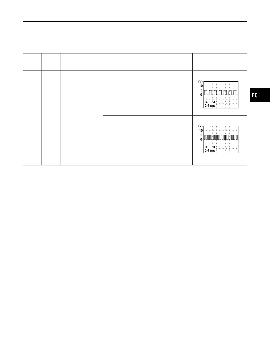
85
Y
Crankshaft position
sensor (POS)
[Engine is running]
I
Idle speed
Approximately 2.4V
SEF057V
[Engine is running]
I
Engine speed is 2,000 rpm.
Approximately 2.3V
SEF058V
On Board Diagnosis Logic
NBEC0193
Malfunction is detected when 1° signal is not entered to ECM for
the first few seconds during engine cranking, or 1° signal is not
entered to ECM during engine running.
Possible Cause
NBEC0493
I
Harness or connectors
(The crankshaft position sensor (POS) circuit is open or
shorted.)
I
Crankshaft position sensor (POS)
I
Starter motor (Refer to EL section.)
I
Starting system circuit (Refer to EL section.)
I
Dead (Weak) battery
GI
MA
EM
LC
FE
AT
TF
PD
AX
SU
BR
ST
RS
BT
HA
SC
EL
IDX
DTC P0335 CRANKSHAFT POSITION SENSOR (CKPS) (POS)
ECM Terminals and Reference Value
EC-335