Infiniti QX4 (R50). Manual - part 216
Diagnostic Procedure
NBEC0190
1
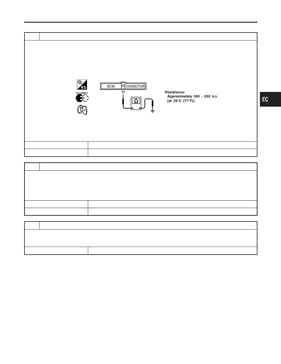
CHECK KNOCK SENSOR INPUT SIGNAL CIRCUIT FOR OPEN AND SHORT-I
1. Turn ignition switch “OFF”.
2. Disconnect ECM harness connector.
3. Check resistance between ECM terminal 93 and engine ground.
NOTE:
It is necessary to use an ohmmeter which can measure more than 10 M
Ω
.
SEF321X
4. Also check harness for short to ground and short to power.
OK or NG
OK
©
GO TO 5.
NG
©
GO TO 2.
2
CHECK KNOCK SENSOR INPUT SIGNAL CIRCUIT FOR OPEN AND SHORT-II
1. Disconnect knock sensor harness connector.
2. Check harness continuity between ECM terminal 93 and knock sensor terminal 2. Refer to Wiring Diagram.
Continuity should exist.
3. Also check harness for short to ground and short to power.
OK or NG
OK
©
GO TO 4.
NG
©
GO TO 3.
3
DETECT MALFUNCTIONING PART
Check the following.
I
Harness connectors F19, F116
I
Harness for open or short between ECM and knock sensor
©
Repair open circuit or short to ground or short to power in harness or connectors.
GI
MA
EM
LC
FE
AT
TF
PD
AX
SU
BR
ST
RS
BT
HA
SC
EL
IDX
DTC P0325 KNOCK SENSOR (KS)
Diagnostic Procedure
EC-331