Infiniti QX4 (R50). Manual - part 200
SEF327R
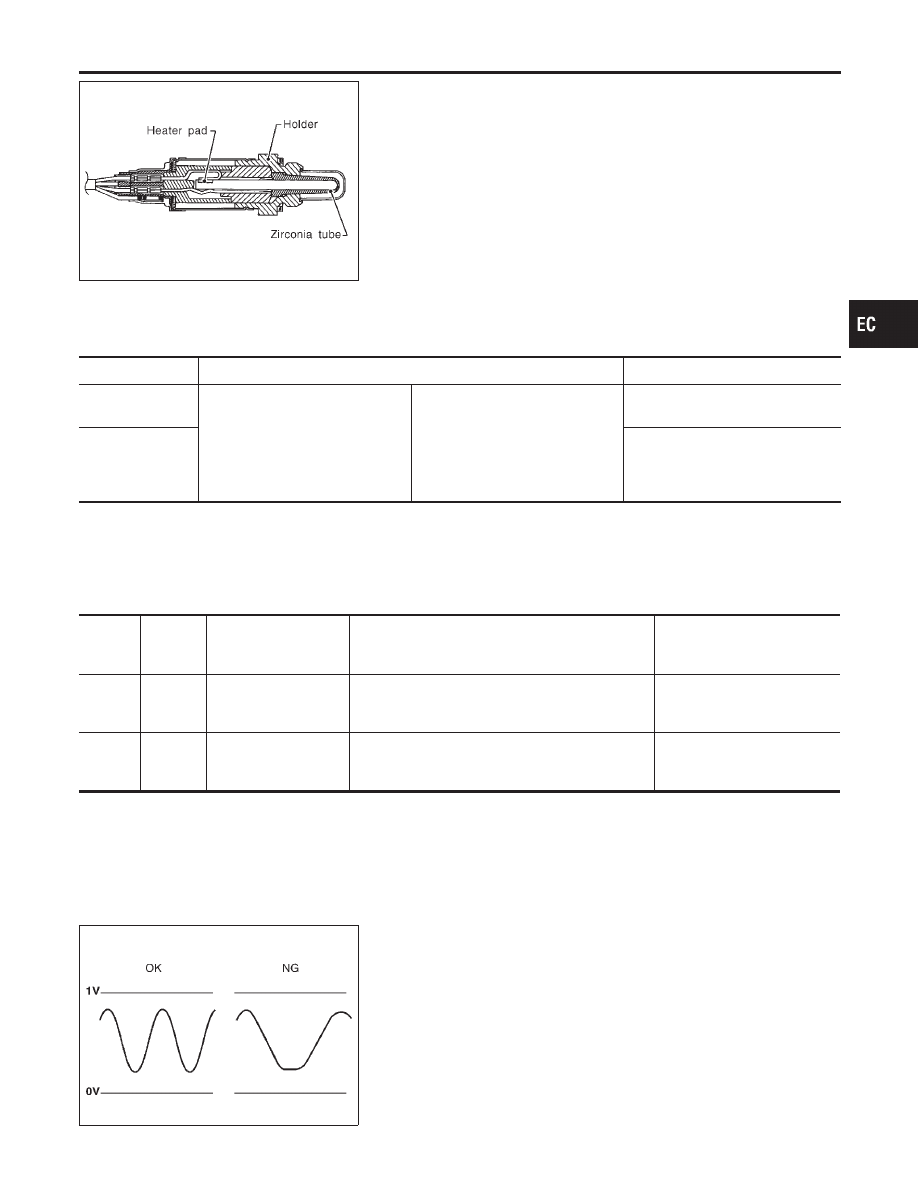
Component Description
NBEC0146
The heated oxygen sensor 2 (rear), after three way catalyst, moni-
tors the oxygen level in the exhaust gas on each bank.
Even if switching characteristics of the heated oxygen sensor 1
(front) are shifted, the air fuel ratio is controlled to stoichiometric,
by the signal from the heated oxygen sensor 2 (rear).
This sensor is made of ceramic zirconia. The zirconia generates
voltage from approximately 1V in richer conditions to 0V in leaner
conditions.
Under normal conditions the heated oxygen sensor 2 (rear) is not
used for engine control operation.
CONSULT-II Reference Value in Data Monitor
Mode
NBEC0147
Specification data are reference values.
MONITOR ITEM
CONDITION
SPECIFICATION
HO2S2 (B1)
HO2S2 (B2)
I
Engine: After warming up
Revving engine from idle up to
2,000 rpm
0 - 0.3V
+,
Approx. 0.6 - 1.0V
HO2S2 MNTR
(B1)
HO2S2 MNTR
(B2)
LEAN
+,
RICH
ECM Terminals and Reference Value
NBEC0660
Specification data are reference values and are measured between each terminal and ground.
CAUTION:
Do not use ECM ground terminals when measuring input/output voltage. Doing so may result in dam-
age to the ECM’s transistor. Use a ground other than ECM terminals, such as the ground.
TERMI-
NAL
NO.
WIRE
COLOR
ITEM
CONDITION
DATA (DC Voltage)
72
OR
Heated oxygen sensor
2 (rear) (bank 1)
[Engine is running]
I
Warm-up condition
I
Engine speed is 2,000 rpm.
0 - Approximately 1.0V
71
OR/L
Heated oxygen sensor
2 (rear) (bank 2)
[Engine is running]
I
Warm-up condition
I
Engine speed is 2,000 rpm.
0 - Approximately 1.0V
SEF302U
On Board Diagnosis Logic
NBEC0149
The heated oxygen sensor 2 (rear) has a much longer switching
time between rich and lean than the heated oxygen sensor 1
(front). The oxygen storage capacity before the three way catalyst
causes the longer switching time. To judge the malfunctions of
heated oxygen sensor 2 (rear), ECM monitors whether the switch-
ing response of the sensor’s voltage is faster than specified during
the various driving condition such as fuel-cut.
Malfunction is detected when it takes more time for the sensor to
respond between rich and lean than the specified time.
GI
MA
EM
LC
FE
AT
TF
PD
AX
SU
BR
ST
RS
BT
HA
SC
EL
IDX
DTC P0139, P0159 HEATED OXYGEN SENSOR 2 (REAR) (BANK 1)/(BANK 2)
(RESPONSE MONITORING)
Component Description
EC-267