Infiniti QX4 (R50). Manual - part 196
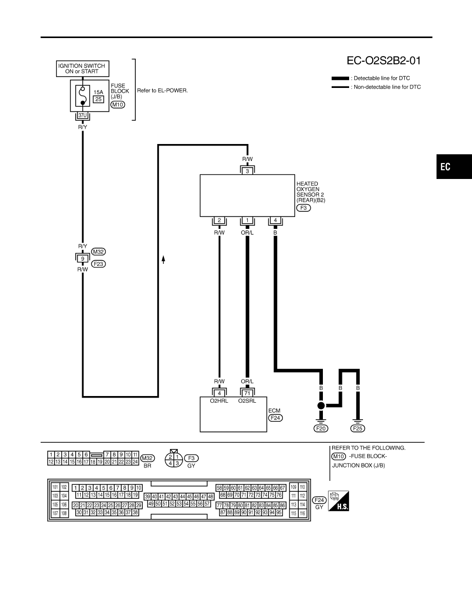
LEFT BANK
NBEC0136S02
MEC952C
GI
MA
EM
LC
FE
AT
TF
PD
AX
SU
BR
ST
RS
BT
HA
SC
EL
IDX
DTC P0137, P0157 HEATED OXYGEN SENSOR 2 (REAR) (BANK 1)/(BANK 2)
(MIN. VOLTAGE MONITORING)
Wiring Diagram (Cont’d)
EC-251
|
|
|
LEFT BANK NBEC0136S02 MEC952C GI MA EM LC FE AT TF PD AX SU BR ST RS BT HA SC EL IDX DTC P0137, P0157 HEATED OXYGEN SENSOR 2 (REAR) (BANK 1)/(BANK 2) (MIN. VOLTAGE MONITORING) Wiring Diagram (Cont’d) EC-251 |