Infiniti QX4 (R50). Manual - part 180


  Index      Infiniti     Infiniti QX4 (R50) - service repair manual 2001 year


Search            copyright infringement  


Content   ..  178  179  180  181   ..


Infiniti QX4 (R50). Manual - part 180


Description

NBEC0081

NOTE:
If DTC P0125 is displayed with P0115, first perform the trouble
diagnosis for DTC P0115. Refer to EC-169.

SEF594K

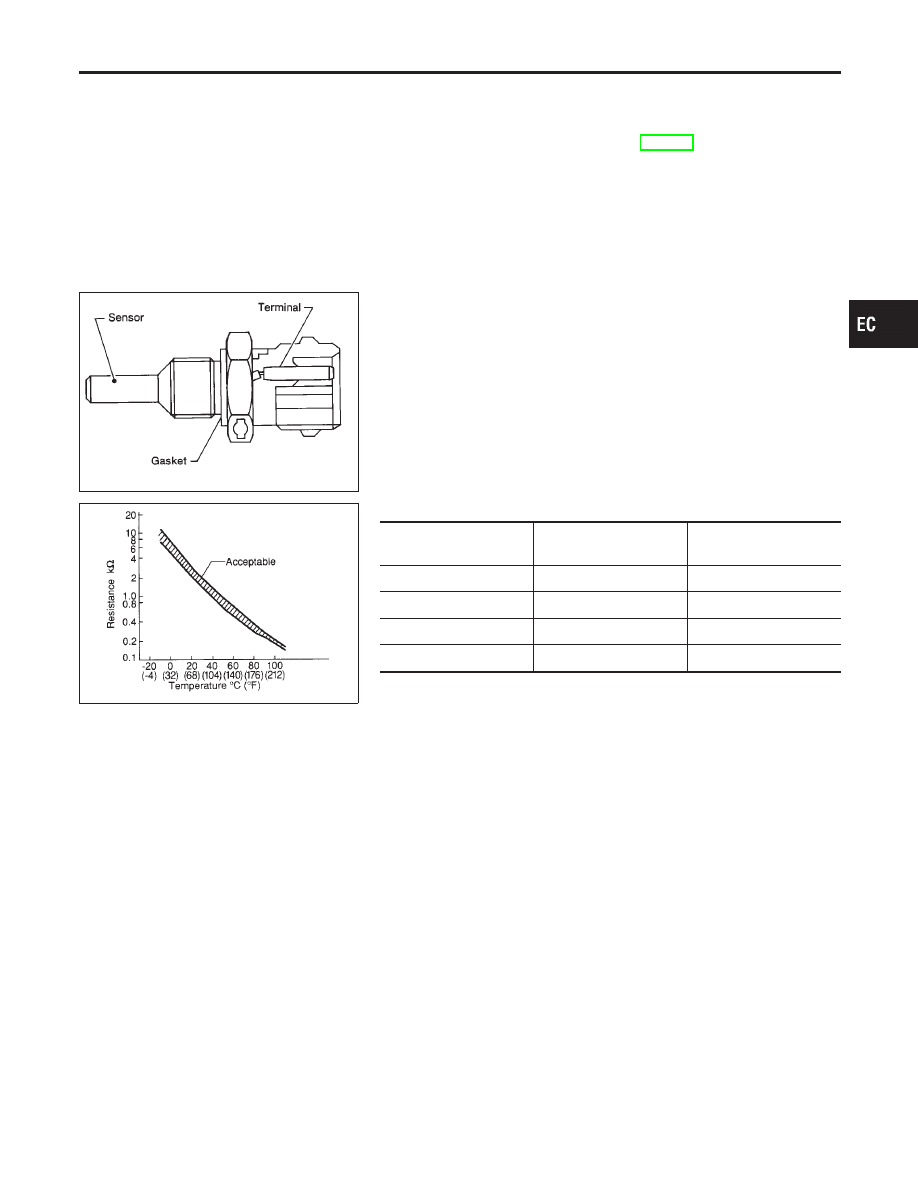
COMPONENT DESCRIPTION

NBEC0081S01

The engine coolant temperature sensor is used to detect the
engine coolant temperature. The sensor modifies a voltage signal
from the ECM. The modified signal returns to the ECM as the
engine coolant temperature input. The sensor uses a thermistor
which is sensitive to the change in temperature. The electrical
resistance of the thermistor decreases as temperature increases.

SEF012P

<Reference data>

Engine coolant

temperature

°C (°F)

Voltage*

V

Resistance

k

−10 (14)

4.4

9.2

20 (68)

3.5

2.1 - 2.9

50 (122)

2.2

0.68 - 1.00

90 (194)

0.9

0.236 - 0.260

*: These data are reference values and are measured between ECM terminal 70
(Engine coolant temperature sensor) and ground.

CAUTION:

Do not use ECM ground terminals when measuring input/
output voltage. Doing so may result in damage to the ECM’s
transistor. Use a ground other than ECM terminals, such as
the ground.

On Board Diagnosis Logic

NBEC0082

Malfunction is detected when voltage sent to ECM from the sen-
sor is not practical, even when some time has passed after start-
ing the engine, or engine coolant temperature is insufficient for
closed loop fuel control.

GI

MA

EM

LC

FE

AT

TF

PD

AX

SU

BR

ST

RS

BT

HA

SC

EL

IDX

DTC P0125 ENGINE COOLANT TEMPERATURE SENSOR (ECTS)

Description

EC-187

Possible Cause

NBEC0431

I

Harness or connectors
(High resistance in the circuit)

I

Engine coolant temperature sensor

I

Thermostat

SEF174Y

DTC Confirmation Procedure

NBEC0083

CAUTION:

Be careful not to overheat engine.
NOTE:
If “DTC Confirmation Procedure” has been previously conducted,
always turn ignition switch “OFF” and wait at least 10 seconds
before conducting the next test.

WITH CONSULT-II

NBEC0083S01

1)

Turn ignition switch “ON”.

2)

Select “DATA MONITOR” mode with CONSULT-II.

3)

Check that “COOLAN TEMP/S” is above 10°C (50°F).
If it is above 10°C (50°F), the test result will be OK.
If it is below 10°C (50°F), go to following step.

4)

Start engine and run it for 65 minutes at idle speed.
If “COOLAN TEMP/S” increases to more than 10°C (50°F)
within 65 minutes, stop engine because the test result will
be OK.

5)

If 1st trip DTC is detected, go to “Diagnostic Procedure”,
EC-190.

WITH GST

NBEC0083S02

Follow the procedure “WITH CONSULT-II” above.

DTC P0125 ENGINE COOLANT TEMPERATURE SENSOR (ECTS)

Possible Cause

EC-188

Wiring Diagram

NBEC0084

MEC945C

GI

MA

EM

LC

FE

AT

TF

PD

AX

SU

BR

ST

RS

BT

HA

SC

EL

IDX

DTC P0125 ENGINE COOLANT TEMPERATURE SENSOR (ECTS)

Wiring Diagram

EC-189

Diagnostic Procedure

NBEC0085

1

CHECK ECTS POWER SUPPLY CIRCUIT

1. Turn ignition switch “OFF”.
2. Disconnect engine coolant temperature sensor harness connector F112, F28.

SEF370Z

3. Turn ignition switch “ON”.
4. Check voltage between ECTS harness connector F28 terminal 3 and ground with CONSULT-II or tester.

SEF371Z

OK or NG

OK

©

GO TO 3.

NG

©

Repair open circuit or short to ground or short to power in harness or connectors.

2

DETECT MALFUNCTIONING PART

Check the following.

I

Harness connectors F112, F28

I

Harness for open or short between ECM and engine coolant temperature sensor

©

Repair harness or connectors.

3

CHECK ECTS GROUND CIRCUIT FOR OPEN AND SHORT

1. Turn ignition switch “OFF”.
2. Check harness continuity between ECTS terminal 2 and engine ground.

Refer to Wiring Diagram.

Continuity should exist.

3. Also check harness for short to power.

OK or NG

OK

©

GO TO 5.

NG

©

GO TO 4.

DTC P0125 ENGINE COOLANT TEMPERATURE SENSOR (ECTS)

Diagnostic Procedure

EC-190


Content   ..  178  179  180  181   ..