Infiniti QX4 (R50). Manual - part 162


  Index      Infiniti     Infiniti QX4 (R50) - service repair manual 2001 year


Search            copyright infringement  


Content   ..  160  161  162  163   ..


Infiniti QX4 (R50). Manual - part 162


31

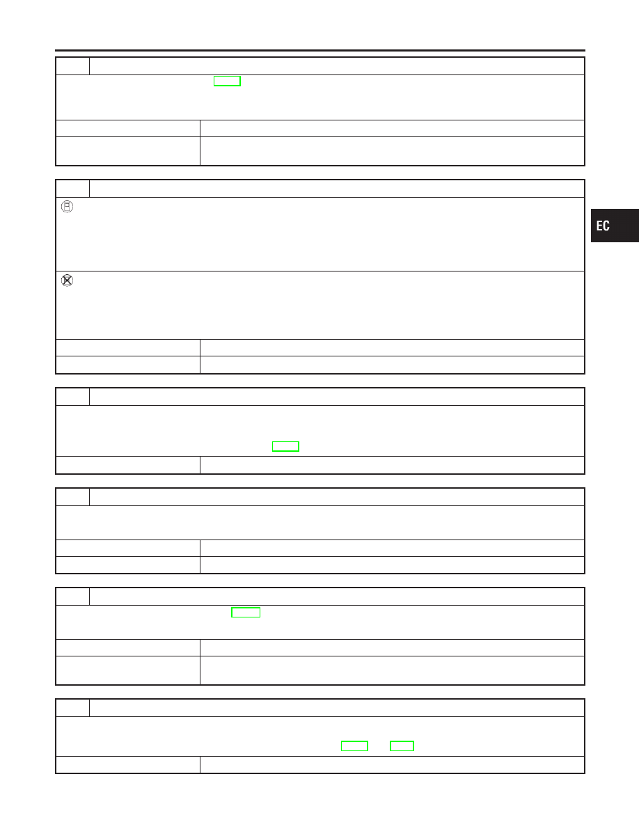
PERFORM IDLE AIR VOLUME LEARNING

Refer to “Idle Air Volume Learning”, EC-57.
Which is the result CMPLT or INCMP?

CMPLT or INCMP

CMPLT

©

GO TO 32.

INCMP

©

1. Follow the construction of “Idle Air volume Learning”.
2. GO TO 31.

32

CHECK TARGET IDLE SPEED AGAIN

With CONSULT-II

1. Start engine and warm it up to normal operating temperature.
2. Select “ENG SPEED” in “DATA MONITOR” mode with CONSULT-II.
3. Check idle speed.

750

±

50 rpm (in “P” or “N” position)

Without CONSULT-II

1. Start engine and warm it up to normal operating temperature.
2. Check idle speed.

750

±

50 rpm (in “P” or “N” position)

OK or NG

OK

©

GO TO 34.

NG

©

GO TO 33.

33

CHECK ECM FUNCTION

1. Substitute another known-good ECM to check ECM function.

(ECM may be the cause of a problem, but this is rarely the case.)

2. Perform initialization of NVIS (NATS) system and registration of NVIS (NATS) ignition key IDs. Refer to “NVIS (NISSAN

VEHICLE IMMOBILIZER SYSTEM — NATS)”, EC-74.

©

GO TO 31.

34

CHECK IGNITION TIMING AGAIN

Check ignition timing again. Refer to Test No. 30.

OK or NG

OK

©

GO TO 36.

NG

©

GO TO 35.

35

CHECK TIMING CHAIN INSTALLATION

Check timing chain installation. Refer to EM-29, “Installation”.

OK or NG

OK

©

GO TO 33.

NG

©

1. Repair the timing chain installation.
2. GO TO 31.

36

ERASE UNNECESSARY DTC

After this inspection, unnecessary DTC No. might be displayed.
Erase the stored memory in ECM and TCM (Transmission control module).
Refer to “How to Erase Emission-Related Diagnostic Information”, EC-72 and AT-35, “HOW TO ERASE DTC”.

©

INSPECTION END

GI

MA

EM

LC

FE

AT

TF

PD

AX

SU

BR

ST

RS

BT

HA

SC

EL

IDX

TROUBLE DIAGNOSIS — BASIC INSPECTION

Basic Inspection (Cont’d)

EC-115

DTC Inspection Priority Chart

NBEC0039

If some DTCs are displayed at the same time, perform inspections one by one based on the following prior-
ity chart.

Priority

Detected items (DTC)

1

I

P0100 Mass air flow sensor

I

P0110 Intake air temperature sensor

I

P0115 P0125 Engine coolant temperature sensor

I

P0120 Throttle position sensor

I

P0180 Fuel tank temperature sensor

I

P0325 Knock sensor

I

P0335 P1336 Crankshaft position sensor (POS)

I

P0340 Camshaft position sensor (PHASE)

I

P0460 P0461 P0464 P1464 Fuel level sensor

I

P0500 Vehicle speed sensor

I

P0605 ECM

I

P1320 Ignition signal

I

P1335 Crankshaft position sensor (REF)

I

P1605 A/T diagnosis communication line

I

P1706 Park/Neutral position (PNP) switch

2

I

P0105 Absolute pressure sensor

I

P0130-P0134, P0150-P0154 Heated oxygen sensor 1 (front)

I

P0135 P0155 Heated oxygen sensor 1 heater (front)

I

P0137-P0140, P0157-P0160 Heated oxygen sensor 2 (rear)

I

P0141 P0161 Heated oxygen sensor 2 (rear) heater

I

P0217 Coolant overtemperature enrichment protection

I

P0443 P1444 EVAP canister purge volume control solenoid valve

I

P0446 P1446 P1448 EVAP canister vent control valve

I

P0450 EVAP control system pressure sensor

I

P0510 Closed throttle position switch

I

P0705-P0755 P1705 P1760 A/T related sensors, solenoid valves and switches

I

P1111 Intake valve timing control solenoid valve

I

P1140 Intake valve timing control position sensor

I

P1165 Swirl control valve control vacuum check switch

I

P1441 EVAP control system (VERY SMALL LEAK)

I

P1447 EVAP control system purge flow monitoring

I

P1490 P1491 Vacuum cut valve bypass valve

3

I

P0171 P0172 P0174 P0175 Fuel injection system function

I

P0306 - P0300 Misfire

I

P0420 P0430 Three way catalyst function

I

P0440 P1440 EVAP control system (SMALL LEAK)

I

P0455 EVAP control system (GROSS LEAK)

I

P0505 IACV-AAC valve

I

P0600 A/T communication line

I

P0731-P0734 P0744 A/T function

I

P1110 Intake valve timing control

I

P1130 Swirl control valve control solenoid valve

I

P1148 P1168 Closed loop control

TROUBLE DIAGNOSIS — GENERAL DESCRIPTION

DTC Inspection Priority Chart

EC-116

Fail-safe Chart

=NBEC0040

The ECM enters fail-safe mode, if any of the following malfunctions is detected due to the open or short cir-
cuit. When the ECM enters the fail-safe mode, the MIL illuminates.

DTC No.

Detected items

Engine operating condition in fail-safe mode

P0100

Mass air flow sensor circuit

Engine speed will not rise more than 2,400 rpm due to the fuel cut.

P0115

Engine coolant temperature
sensor circuit

Engine coolant temperature will be determined by ECM based on the time after
turning ignition switch “ON” or “START”.
CONSULT-II displays the engine coolant temperature decided by ECM.

Condition

Engine coolant temperature decided

(CONSULT-II display)

Just as ignition switch is turned
ON or Start

40°C (104°F)

More than approx. 4 minutes
after ignition ON or Start

80°C (176°F)

Except as shown above

40 - 80°C (104 - 176°F)

(Depends on the time)

P0120

Throttle position sensor cir-
cuit

Throttle position will be determined based on the injected fuel amount and the
engine speed.
Therefore, acceleration will be poor.

Condition

Driving condition

When engine is idling

Normal

When accelerating

Poor acceleration

P1335

Crankshaft position sensor
(REF) circuit

Compression TDC signal (120° signal) is controlled by camshaft position sensor
(PHASE) signal and crankshaft position sensor (POS) signal. Ignition timing will be
delayed 0° to 2°.

Unable to
access ECM

ECM

ECM fail-safe activating condition
The computing function of the ECM was judged to be malfunctioning.
When the fail-safe system activates (i.e., if the ECM detects a malfunction condi-
tion in the CPU of ECM), the MIL on the instrument panel lights to warn the driver.
However it is not possible to access ECM and DTC cannot be confirmed.
Engine control with fail-safe
When ECM fail-safe is operating, fuel injection, ignition timing, fuel pump operation,
IACV-AAC valve operation and cooling fan operation are controlled under certain
limitations.

ECM fail-safe operation

Engine speed

Engine speed will not rise more than 3,000

rpm

Fuel injection

Simultaneous multiport fuel injection system

Ignition timing

Ignition timing is fixed at the preset valve

Fuel pump

Fuel pump relay is “ON” when engine is running

and “OFF” when engine stalls

IACV-AAC valve

Full open

Replace ECM, if ECM fail-safe condition is confirmed.

GI

MA

EM

LC

FE

AT

TF

PD

AX

SU

BR

ST

RS

BT

HA

SC

EL

IDX

TROUBLE DIAGNOSIS — GENERAL DESCRIPTION

Fail-safe Chart

EC-117

Symptom Matrix Chart

NBEC0041

SYSTEM — BASIC ENGINE CONTROL SYSTEM

NBEC0041S01

SYMPTOM

Reference
page

HARD/NO

ST

AR

T/REST

AR

T

(EXCP

.

HA)

ENGINE

ST

ALL

HESIT

A

TION/SURGING/FLA

T

SPOT

SP

ARK

KNOCK/DET

ONA

TION

LACK

OF

POWER/POOR

ACCELERA

TION

HIGH

IDLE/LOW

IDLE

ROUGH

IDLE/HUNTING

IDLING

VIBRA

TION

SLOW/NO

RETURN

T

O

IDLE

OVERHEA

TS/W

A

TER

TEMPERA

TURE

HIGH

EXCESSIVE

FUEL

CONSUMPTION

EXCESSIVE

OIL

CONSUMPTION

BA

TTER

Y

DEAD

(UNDER

CHARGE)

Warranty symptom code

AA AB AC AD AE AF AG

AH

AJ

AK AL AM HA

Fuel

Fuel pump circuit

1

1

2

3

2

2

2

3

2

EC-625

Fuel pressure regulator system

3

3

4

4

4

4

4

4

4

4

EC-40

Injector circuit

1

1

2

3

2

2

2

2

EC-616

Evaporative emission system

3

3

4

4

4

4

4

4

4

4

EC-32

Air

Positive crankcase ventilation sys-
tem

1

EC-38

Incorrect idle speed adjustment

1

1

1

1

1

EC-101

IACV-AAC valve circuit

1

1

2

3

3

2

2

2

2

2

2

EC-422

Ignition

Incorrect ignition timing adjustment

3

3

1

1

1

1

1

1

EC-101

Ignition circuit

1

1

2

2

2

2

2

2

EC-499

Main power supply and ground circuit

2

2

3

3

3

3

3

2

3

EC-142

Air conditioner circuit

3

3

2

HA section

1 - 6: The numbers refer to the order of inspection.
(continued on next page)

TROUBLE DIAGNOSIS — GENERAL DESCRIPTION

Symptom Matrix Chart

EC-118


Content   ..  160  161  162  163   ..