Infiniti QX4 (R50). Manual - part 160


  Index      Infiniti     Infiniti QX4 (R50) - service repair manual 2001 year


Search            copyright infringement  


Content   ..  158  159  160  161   ..


Infiniti QX4 (R50). Manual - part 160


13

ADJUSTMENT THROTTLE POSITION SWITCH CLOSED POSITION-II

With CONSULT-II

1. Temporarily tighten sensor body fixing bolts as follows.

I

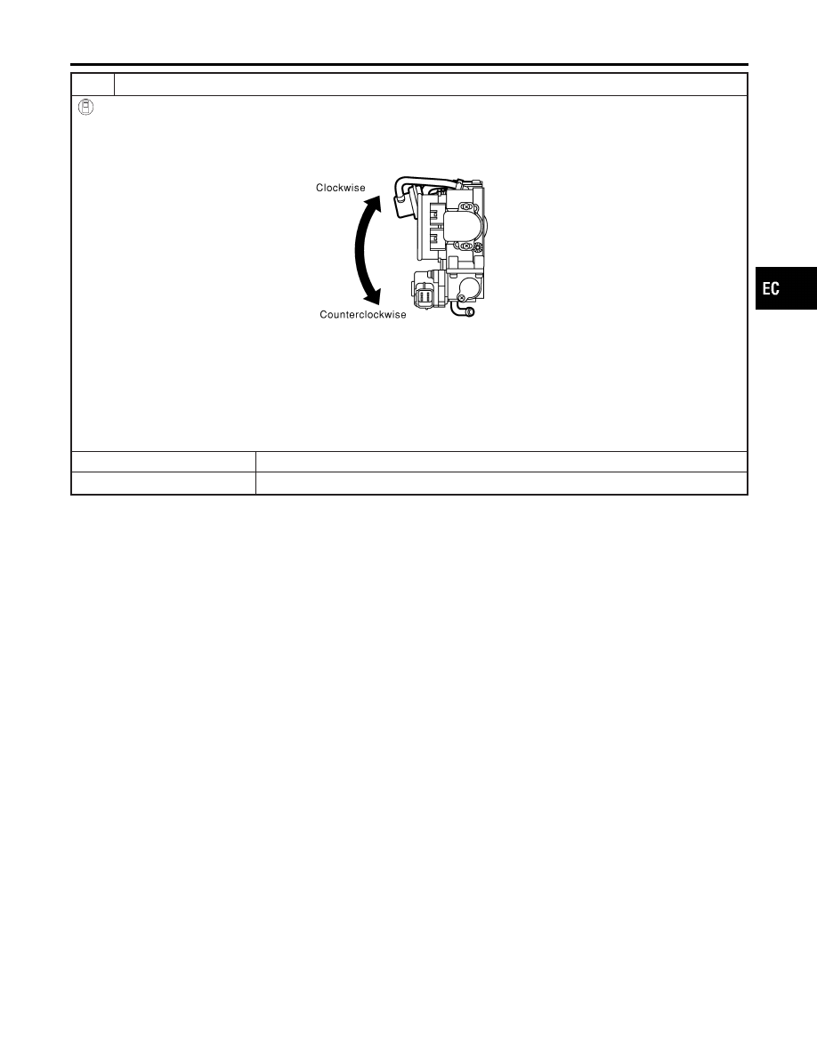
Gradually move the sensor body clockwise and stop it when “CLSD THL/P SW” signal switches from “OFF” to
“ON”, then temporarily tighten sensor body fixing bolts.

SEF954Y

2. Make sure two or three times that the signal is “ON” when the throttle valve is closed and “OFF” when it is opened.
3. Remove 0.05 mm (0.0020 in) feeler gauge then insert 0.15 mm (0.0059 in) feeler gauge.
4. Make sure two or three times that the signal remains “OFF” when the throttle valve is closed.
5. Tighten throttle position sensor.
6. Check the “CLSD THL/P SW” signal again.

The signal remains “OFF” while closing throttle valve.

OK or NG

OK

©

GO TO 14.

NG

©

GO TO 12.

GI

MA

EM

LC

FE

AT

TF

PD

AX

SU

BR

ST

RS

BT

HA

SC

EL

IDX

TROUBLE DIAGNOSIS — BASIC INSPECTION

Basic Inspection (Cont’d)

EC-107

14

RESET THROTTLE POSITION SENSOR IDLE POSITION MEMORY

With CONSULT-II

NOTE:
Always warm up engine to normal operating temperature. If engine is cool, the throttle position sensor idle posi-
tion memory will not be reset correctly.
1. Confirm that proper vacuum is applied. Refer to Test No. 10.
2. Attach blind cap to vacuum port from which vacuum hose to throttle opener was disconnected.
3. Start engine.
4. Warm up engine to normal operating temperature.
5. Select “TP SW/TP SEN IDLE POSI ADJ” in “WORK SUPPORT” mode.
6. Stop engine. (Turn ignition switch “OFF”.)
7. Turn ignition switch “ON” and wait at least 5 seconds.

SEF864V

8. Turn ignition switch “OFF” and wait at least 10 seconds.
9. Repeat steps 7 and 8 until “CLSD THL POS” signal changes to “ON”.

SEF987Y

©

GO TO 19.

TROUBLE DIAGNOSIS — BASIC INSPECTION

Basic Inspection (Cont’d)

EC-108

15

CHECK THROTTLE POSITION SWITCH CLOSED POSITION-II

1. Disconnect closed throttle position switch harness connector.
2. Check continuity between closed throttle position switch terminals and under the following conditions.

SEF330Z

I

Insert the 0.05 mm (0.0020 in) and 0.15 mm (0.0059 in) feeler gauge alternately between the stopper and throttle drum
as shown in the figure.

SEF953Y

“Continuity should exist” while inserting 0.05 mm (0.0020 in) feeler gauge.
“Continuity should not exist” while inserting 0.15 mm (0.0059 in) feeler gauge.

OK or NG

OK

©

GO TO 18.

NG

©

GO TO 16.

GI

MA

EM

LC

FE

AT

TF

PD

AX

SU

BR

ST

RS

BT

HA

SC

EL

IDX

TROUBLE DIAGNOSIS — BASIC INSPECTION

Basic Inspection (Cont’d)

EC-109

16

ADJUSTMENT THROTTLE POSITION SWITCH CLOSED POSITION-I

1. Loosen throttle position sensor fixing bolts.
2. Confirm that proper vacuum is applied. Refer to Test No. 10. During adjustment, vacuum should be applied.
3. Insert 0.05 mm (0.0020 in) feeler gauge between stopper and throttle drum as shown in the figure.

SEF953Y

SEF330Z

4. Turn throttle position sensor body counterclockwise until continuity does not exist.

SEF954Y

©

GO TO 17.

TROUBLE DIAGNOSIS — BASIC INSPECTION

Basic Inspection (Cont’d)

EC-110


Content   ..  158  159  160  161   ..