Infiniti QX4 (R50). Manual - part 150


  Index      Infiniti     Infiniti QX4 (R50) - service repair manual 2001 year


Search            copyright infringement  


Content   ..  148  149  150  151   ..


Infiniti QX4 (R50). Manual - part 150


I

The time required for each diagnosis varies with road surface conditions, weather, altitude, individual driv-
ing habits, etc.
Zone A refers to the range where the time required, for the diagnosis under normal conditions*, is the
shortest.
Zone B refers to the range where the diagnosis can still be performed if the diagnosis is not completed
within zone A.

*: Normal conditions refer to the following:

Sea level

Flat road

Ambient air temperature: 20 - 30°C (68 - 86°F)

Diagnosis is performed as quickly as possible under normal conditions.
Under different conditions [For example: ambient air temperature other than 20 - 30°C (68 - 86°F)], diag-
nosis may also be performed.

Pattern 1:

I

The engine is started at the engine coolant temperature of −10 to 35°C (14 to 95°F)
(where the voltage between the ECM terminal 70 and ground is 3.0 - 4.3V).

I

The engine must be operated at idle speed until the engine coolant temperature is greater than 70°C
(158°F) (where the voltage between the ECM terminal 70 and ground is lower than 1.4V).

I

The engine is started at the fuel tank temperature of warmer than 0°C (32°F) (where the voltage
between the ECM terminal 92 and ground is less than 4.1V).

Pattern 2:

I

When steady-state driving is performed again even after it is interrupted, each diagnosis can be conducted.
In this case, the time required for diagnosis may be extended.

Pattern 3:

I

The driving pattern outlined in *2 must be repeated at least 3 times.

Pattern 4:

I

Tests are performed after the engine has been operated for at least 17 minutes.

I

The accelerator pedal must be held very steady during steady-state driving.

I

If the accelerator pedal is moved, the test must be conducted all over again.

*1: Depress the accelerator pedal until vehicle speed is 90 km/h (56 MPH), then release the accelerator pedal
and keep it released for more than 10 seconds. Depress the accelerator pedal until vehicle speed is 90 km/h
(56 MPH) again.
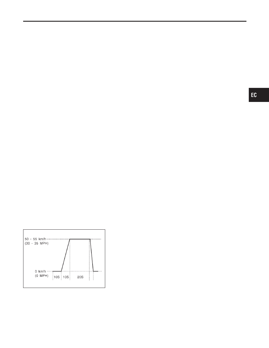
*2: Operate the vehicle in the following driving pattern.
1) Decelerate vehicle to 0 km/h (0 MPH) and let engine idle.
2) Repeat driving pattern shown below at least 10 times.

I

During acceleration, hold the accelerator pedal as steady as possible.

SEF414S

*3: Checking the vehicle speed with GST is advised.
Suggested Transmission Gear Position for A/T Models
Set the selector lever in the “D” position with the overdrive switch turned ON.
Suggested upshift speeds for M/T models
Shown below are suggested vehicle speeds for shifting into a higher gear. These suggestions relate to fuel
economy and vehicle performance. Actual upshift speeds will vary according to road conditions, the weather
and individual driving habits.

GI

MA

EM

LC

FE

AT

TF

PD

AX

SU

BR

ST

RS

BT

HA

SC

EL

IDX

ON BOARD DIAGNOSTIC SYSTEM DESCRIPTION

Emission-related Diagnostic Information (Cont’d)

EC-67

For normal acceleration in low altitude areas

[less than 1,219 m (4,000 ft)]:

For quick acceleration in low altitude
areas and high altitude areas
[over 1,219 m (4,000 ft)]:

Gear change

ACCEL shift point

km/h (MPH)

CRUISE shift point

km/h (MPH)

km/h (MPH)

1st to 2nd

21 (13)

21 (13)

24 (15)

2nd to 3rd

37 (23)

26 (16)

40 (25)

3rd to 4th

53 (33)

44 (27)

64 (40)

4th to 5th

63 (39)

58 (36)

72 (45)

Suggested Maximum Speed in Each Gear
Downshift to a lower gear if the engine is not running smoothly, or if you need to accelerate.
Do not exceed the maximum suggested speed (shown below) in any gear. For level road driving, use the
highest gear suggested for that speed. Always observe posted speed limits and drive according to the road
conditions to ensure safe operation. Do not over-rev the engine when shifting to a lower gear as it may cause
engine damage or loss of vehicle control.

Gear

km/h (MPH)

1st

50 (30)

2nd

89 (55)

3rd

128 (80)

4th

5th

TEST VALUE AND TEST LIMIT (GST ONLY — NOT APPLICABLE TO CONSULT-II)

NBEC0031S04

The following is the information specified in Mode 6 of SAE J1979.
The test value is a parameter used to determine whether a system/circuit diagnostic test is “OK” or “NG” while
being monitored by the ECM during self-diagnosis. The test limit is a reference value which is specified as the
maximum or minimum value and is compared with the test value being monitored.
Items for which these data (test value and test limit) are displayed are the same as SRT code items (30 test
items).
These data (test value and test limit) are specified by Test ID (TID) and Component ID (CID) and can be dis-
played on the GST screen.

X: Applicable

—: Not applicable

SRT item

Self-diagnostic test item

Test value (GST display)

Test limit

Application

TID

CID

CATALYST

Three way catalyst function

(Right bank)

01H

01H

Max.

X

Three way catalyst function

(Left bank)

03H

02H

Max.

X

EVAP SYSTEM

EVAP control system

(Small leak)

05H

03H

Max.

X

EVAP control system purge flow

monitoring

06H

83H

Min.

X

ON BOARD DIAGNOSTIC SYSTEM DESCRIPTION

Emission-related Diagnostic Information (Cont’d)

EC-68

SRT item

Self-diagnostic test item

Test value (GST display)

Test limit

Application

TID

CID

O2 SENSOR

Heated oxygen sensor 1 (front)

(bank 1)

09H

04H

Max.

X

0AH

84H

Min.

X

0BH

04H

Max.

X

0CH

04H

Max.

X

0DH

04H

Max.

X

Heated oxygen sensor 1 (front)

(bank 2)

11H

05H

Max.

X

12H

85H

Min.

X

13H

05H

Max.

X

14H

05H

Max.

X

15H

05H

Max.

X

Heated oxygen sensor 2 (rear)

(bank 1)

19H

86H

Min.

X

1AH

86H

Min.

X

1BH

06H

Max.

X

1CH

06H

Max.

X

Heated oxygen sensor 2 (rear)

(bank 2)

21H

87H

Min.

X

22H

87H

Min.

X

23H

07H

Max.

X

24H

07H

Max.

X

O2 SENSOR HEATER

Heated oxygen sensor 1 (front) heater

(bank 1)

29H

08H

Max.

X

2AH

88H

Min.

X

Heated oxygen sensor 1 (front) heater

(bank 2)

2BH

09H

Max.

X

2CH

89H

Min.

X

Heated oxygen sensor 2 (rear) heater

(bank 1)

2DH

0AH

Max.

X

2EH

8AH

Min.

X

Heated oxygen sensor 2 (rear) heater

(bank 2)

2FH

0BH

Max.

X

30H

8BH

Min.

X

EMISSION-RELATED DIAGNOSTIC INFORMATION ITEMS

NBEC0031S05

X: Applicable

—: Not applicable

Items

(CONSULT-II screen terms)

DTC*1

SRT code

Test value/ Test

limit

(GST only)

1st trip DTC*1

Reference page

NO DTC IS DETECTED.
FURTHER TESTING
MAY BE REQUIRED.

P0000

MAF SEN/CIRCUIT

P0100

X

EC-150

ABSL PRES SEN/CIRC

P0105

X

EC-158

AIR TEMP SEN/CIRC

P0110

X

EC-164

COOLANT T SEN/CIRC

P0115

X

EC-169

GI

MA

EM

LC

FE

AT

TF

PD

AX

SU

BR

ST

RS

BT

HA

SC

EL

IDX

ON BOARD DIAGNOSTIC SYSTEM DESCRIPTION

Emission-related Diagnostic Information (Cont’d)

EC-69

Items

(CONSULT-II screen terms)

DTC*1

SRT code

Test value/ Test

limit

(GST only)

1st trip DTC*1

Reference page

THRTL POS SEN/CIRC

P0120

X

EC-174

*COOLAN T SEN/CIRC

P0125

X

EC-187

HO2S1 (B1)

P0130

X

X

X*2

EC-192

HO2S1 (B1)

P0131

X

X

X*2

EC-202

HO2S1 (B1)

P0132

X

X

X*2

EC-210

HO2S1 (B1)

P0133

X

X

X*2

EC-218

HO2S1 (B1)

P0134

X

X

X*2

EC-231

HO2S1 HTR (B1)

P0135

X

X

X*2

EC-240

HO2S2 (B1)

P0137

X

X

X*2

EC-247

HO2S2 (B1)

P0138

X

X

X*2

EC-257

HO2S2 (B1)

P0139

X

X

X*2

EC-267

HO2S2 (B1)

P0140

X

X

X*2

EC-277

HO2S2 HTR (B1)

P0141

X

X

X*2

EC-286

HO2S1 (B2)

P0150

X

X

X*2

EC-192

HO2S1 (B2)

P0151

X

X

X*2

EC-202

HO2S1 (B2)

P0152

X

X

X*2

EC-210

HO2S1 (B2)

P0153

X

X

X*2

EC-218

HO2S1 (B2)

P0154

X

X

X*2

EC-231

HO2S1 HTR (B2)

P0155

X

X

X*2

EC-240

HO2S2 (B2)

P0157

X

X

X*2

EC-247

HO2S2 (B2)

P0158

X

X

X*2

EC-257

HO2S2 (B2)

P0159

X

X

X*2

EC-267

HO2S2 (B2)

P0160

X

X

X*2

EC-277

HO2S2 HTR (B2)

P0161

X

X

X*2

EC-286

FUEL SYS-LEAN/BK1

P0171

X

EC-294

FUEL SYS-RICH/BK1

P0172

X

EC-302

FUEL SYS-LEAN/BK2

P0174

X

EC-294

FUEL SYS-RICH/BK2

P0175

X

EC-302

FUEL TEMP SEN/CIRC

P0180

X

EC-309

ENG OVER TEMP

P0217

X

EC-314

MULTI CYL MISFIRE

P0300

X

EC-320

CYL 1 MISFIRE

P0301

X

EC-320

CYL 2 MISFIRE

P0302

X

EC-320

CYL 3 MISFIRE

P0303

X

EC-320

CYL 4 MISFIRE

P0304

X

EC-320

CYL 5 MISFIRE

P0305

X

EC-320

CYL 6 MISFIRE

P0306

X

EC-320

ON BOARD DIAGNOSTIC SYSTEM DESCRIPTION

Emission-related Diagnostic Information (Cont’d)

EC-70


Content   ..  148  149  150  151   ..