Infiniti QX4 (R50). Manual - part 147
31
CHECK “CO” %
With CONSULT-II
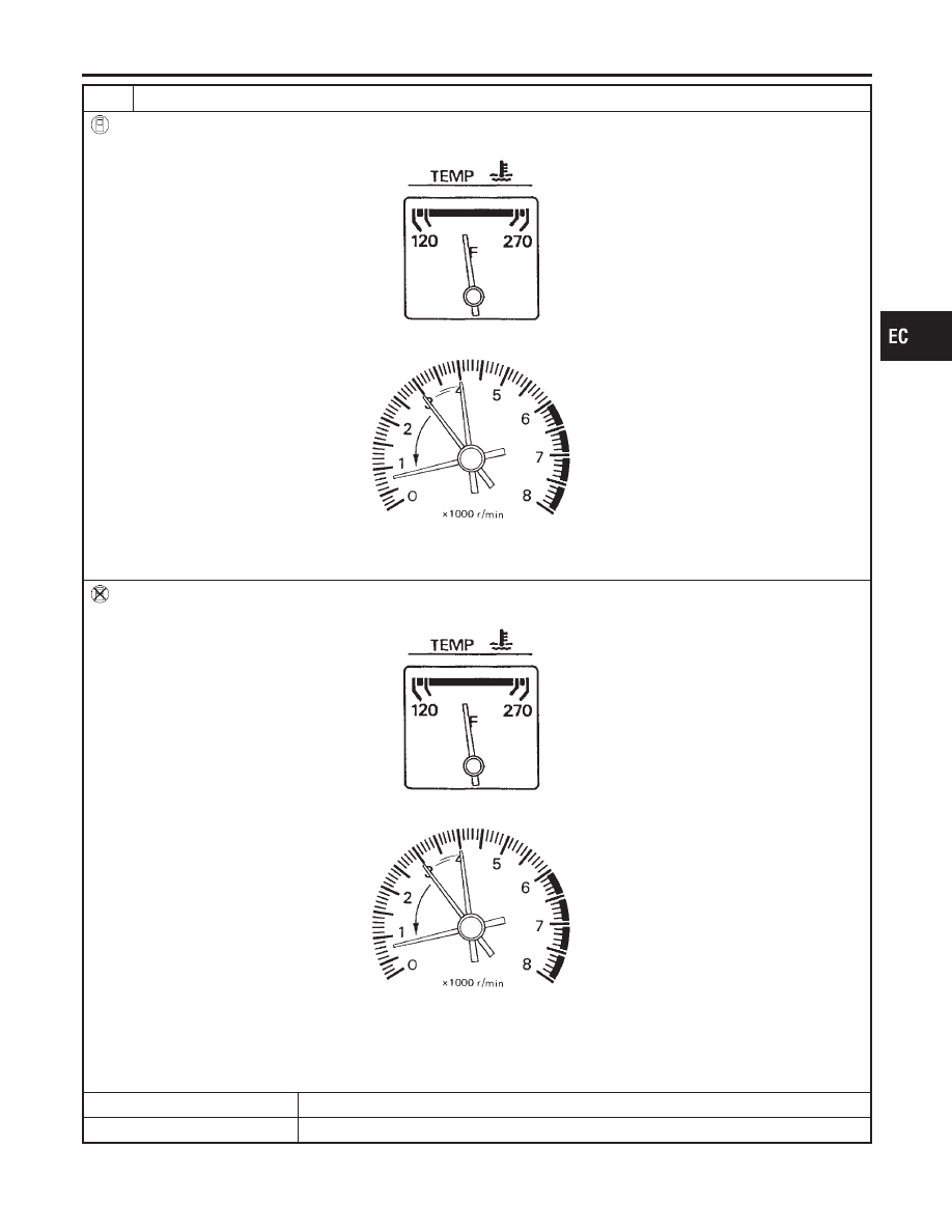
1. Start engine and warm it up until engine coolant temperature indicator points to the middle of gauge.
SEF976U
2. Rev engine (2,000 to 3,000 rpm) two or three times under no-load, then run engine at idle speed.
SEF978U
3. Check “CO” %.
Idle CO: 1.0 - 9.5%
Without CONSULT-II
1. Start engine and warm it up until engine coolant temperature indicator points to the middle of gauge.
SEF976U
2. Rev engine (2,000 to 3,000 rpm) two or three times under no-load, then run engine at idle speed.
SEF978U
3. Check “CO” %.
4. After checking CO%,
a. Disconnect the resistor from terminals of engine coolant temperature sensor.
b. Connect engine coolant temperature sensor harness connector to engine coolant temperature sensor.
OK or NG
OK
©
GO TO 32.
NG
©
GO TO 33.
GI
MA
EM
LC
FE
AT
TF
PD
AX
SU
BR
ST
RS
BT
HA
SC
EL
IDX
BASIC SERVICE PROCEDURE
Idle Speed/Ignition Timing/Idle Mixture Ratio Adjustment (Cont’d)
EC-55