Infiniti QX4 (R50). Manual - part 143
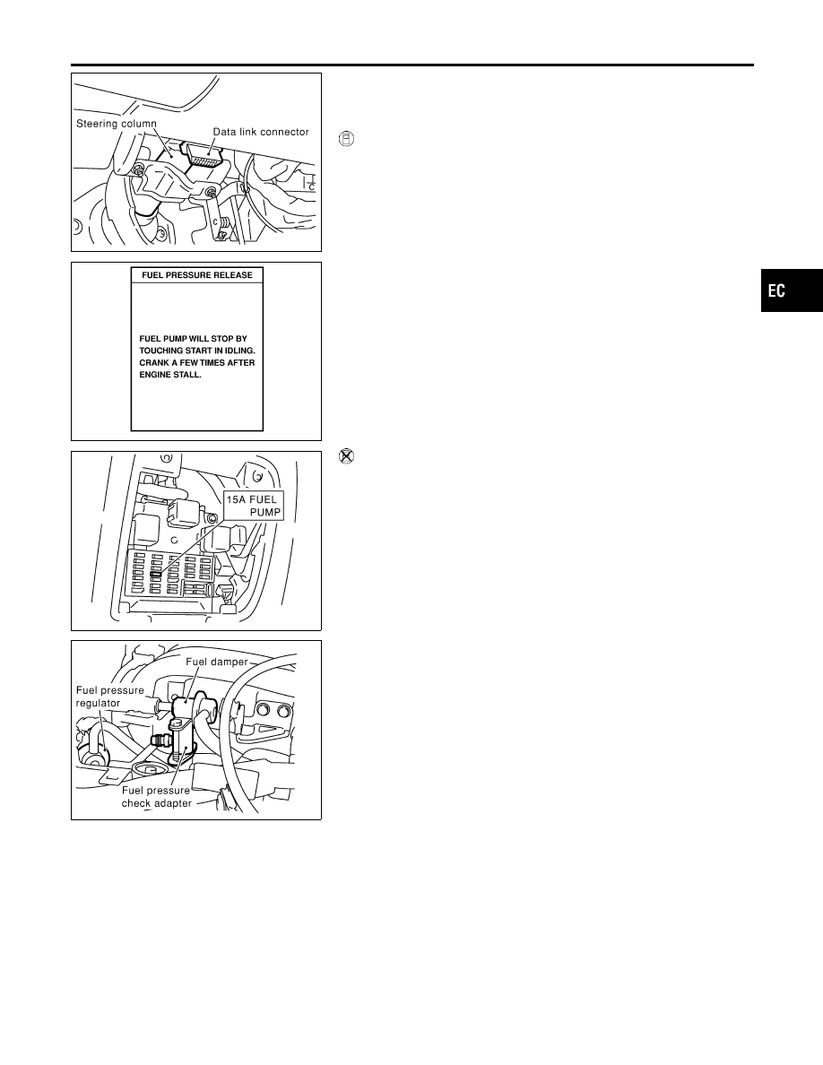
SEF941Y
SEF214Y
Fuel Pressure Release
NBEC0023
Before disconnecting fuel line, release fuel pressure from fuel
line to eliminate danger.
WITH CONSULT-II
NBEC0023S01
1.
Turn ignition switch “ON”.
2.
Perform “FUEL PRESSURE RELEASE” in “WORK SUP-
PORT” mode with CONSULT-II.
3.
Start engine.
4.
After engine stalls, crank it two or three times to release all fuel
pressure.
5.
Turn ignition switch “OFF”.
SEF933Y
WITHOUT CONSULT-II
NBEC0023S02
1.
Remove fuel pump fuse located in fuse box.
2.
Start engine.
3.
After engine stalls, crank it two or three times to release all fuel
pressure.
4.
Turn ignition switch “OFF”.
5.
Reinstall fuel pump fuse after servicing fuel system.
SEF327Z
Fuel Pressure Check
NBEC0024
I
When reconnecting fuel line, always use new clamps.
I
Make sure that clamp screw does not contact adjacent
parts.
I
Use a torque driver to tighten clamps.
I
Use Pressure Gauge to check fuel pressure.
I
Do not perform fuel pressure check with system operat-
ing. Fuel pressure gauge may indicate false readings.
1.
Release fuel pressure to zero.
2.
Disconnect fuel tube joint between fuel damper and injector
tube and set fuel pressure check adapter (J44321).
GI
MA
EM
LC
FE
AT
TF
PD
AX
SU
BR
ST
RS
BT
HA
SC
EL
IDX
BASIC SERVICE PROCEDURE
Fuel Pressure Release
EC-39