Infiniti QX4 (R50). Manual - part 112
Motor Relay or Motor
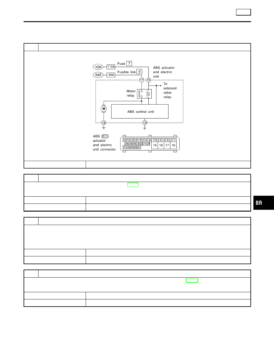
DIAGNOSTIC PROCEDURE
=NBBR0104
Malfunction code No. 61
1
INSPECTION START
ABS motor relay inspection
SBR491E
©
GO TO 2.
2
CHECK FUSIBLE LINK
Check 40A fusible link d. For fusible link layout, refer to EL-16, “POWER SUPPLY ROUTING”.
Is fusible link OK?
Yes
©
GO TO 3.
No
©
GO TO 6.
3
CHECK CONNECTOR
1. Disconnect ABS actuator and electric unit connector. Check terminals for damage or loose connection. Then reconnect
connector.
2. Carry out self-diagnosis again.
Does warning lamp activate again?
Yes
©
GO TO 4.
No
©
INSPECTION END
4
CHECK ABS ACTUATOR AND ELECTRIC UNIT GROUND CIRCUIT
Refer to “ABS ACTUATOR AND ELECTRIC UNIT GROUND” in “Ground Circuit Check”, BR-53.
Is ground circuit OK?
Yes
©
GO TO 5.
No
©
Repair harness or connector.
GI
MA
EM
LC
EC
FE
AT
TF
PD
AX
SU
ST
RS
BT
HA
SC
EL
IDX
TROUBLE DIAGNOSES FOR SELF-DIAGNOSTIC ITEMS
ABS
Motor Relay or Motor
BR-61