Infiniti QX4 (R50). Manual - part 77
SAT681A
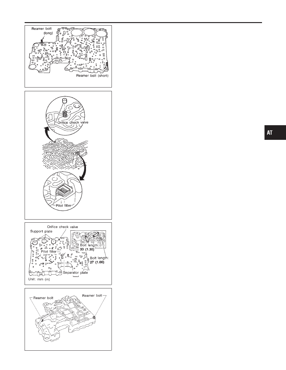
b.
Install reamer bolts from bottom of upper body.
SAT682A
c.
Place oil circuit of lower body face up. Install orifice check
spring, orifice check valve and pilot filter.
SAT197B
d.
Install lower separator plate on lower body.
e.
Install and temporarily tighten support plates, A/T fluid tem-
perature sensor and tube brackets.
SAT198B
f.
Temporarily assemble lower and upper bodies, using reamer
bolt as a guide.
I
Be careful not to dislocate or drop steel balls, orifice
check spring, orifice check valve and pilot filter.
GI
MA
EM
LC
EC
FE
TF
PD
AX
SU
BR
ST
RS
BT
HA
SC
EL
IDX
REPAIR FOR COMPONENT PARTS
Control Valve Assembly (Cont’d)
AT-305